
Related Manuals for Seitron RKP01M

Summary of Contents for Seitron RKP01M
- Page 3 ─────────────────────────── ─────────────────────────── CONTENTS OF THE PACKAGE OPTIONAL COMPONENTS ──────────────────────────── ──────────────────────────── CLIMATE CONTROL UNIT (1 piece) ROOM TEMPERATURE PROBE Code RK P01M Code ST AD01 EXTERNAL TEMPERATURE PROBE (1 piece) REMOTE CONTROL Code ST ED01 Code ACC RK3 COM SUPPLY/RETURN TEMPERATURE PROBE (2 pcs) RELAY MODULE TO CONVERT LIVE CONTACTS TO VOLTAGE FREE CONTACTS Code ST CD02...
- Page 4 ─────────────────────────── ────────────────────────── MAIN CHARACTERISTICS TECHNICAL FEATURES ──────────────────────────── ─────────────────────────── - Power supply 230V~ Power supply: ±230V~ ±10% 50/60Hz - 4 outputs (3 on/off under power + 1 with voltage free Maximum consumption: <1,5 VA contacts) Type of sensors: NTC 10K @25°C B3977 - 6 inputs (4 probes + 1 ambient remote control + 1 Sensor operation limit: -20 °C ..
- Page 5 ─────────────────────────── 4. Secure the base of the unit to the wall. INSTALLATION ─────────────────────────── WARNING - The installer must abide by all applicable technical standards in order to ensure the safety of the system. - Before making any connections, make sure that the mains is disconnected.
- Page 6 8. Make the electrical connections according to the hydraulic diagram chosen in the installer parameter "P1 SCH". Following are the descriptions of the four systems possible. LEGEND: Hydraulic diagram 'SCH_1': Heating system with the control of a 3-point servo motor and a TAF OFF: Enable / Disable anti-freeze circulation pump.
- Page 7 LEGEND: Hydraulic diagram 'SCH_2': Heating system with the control of a 3-point servo motor, a TAC OFF: Enable / Disable anti-condensation circulation pump, an anticondensate pump and a return water function temperature probe. TAC: Anti-condensation temperature This diagram provides for the use of the recirculation pump and TAF OFF: Enable / Disable anti-freeze the return probe -.Tr.
- Page 8 LEGEND: Hydraulic diagram 'SCH_3': Heating system with the 2-point control (ON/OFF) of a single TAC OFF: Enable / Disable TAC function stage burner and a circulation pump. TAC: Anti-condensation temperature This diagram provides for the use of the recirculation pump and TAF OFF: Enable / Disable TAF function the return probe -.Tr.
- Page 9 LEGEND: Hydraulic system 'SCH_4': TCO OFF: Enable / Disable Cut-Off Heating system with the control of a two-stage burner and a circulation pump. TCO: Cut-Off temperature This diagram provides for the use of the recirculation pump and DEL: Pump OFF delay the return probe -.Tr.
- Page 10 OPERATING LOGIC Operating logic in accordance with the hydraulic diagram 'SCH_1' (see page 6): Unit ON Unit OFF Operating logic in accordance with the hydraulic diagram 'SCH_2' (see page 7): Unit ON Unit OFF 10/36 RKP01M0000SE 033955 290120...
- Page 11 Operating logic in accordance with the hydraulic diagram 'SCH_3' (see page 8): Unit ON Unit OFF Operating logic in accordance with the hydraulic diagram 'SCH_4' (see page 9): Unit ON Unit OFF 11/36 RKP01M0000SE 033955 290120...
- Page 12 NOTES FOR THE ELECTRICAL CONNECTIONS The following page shows the resistance values of WARNING the probes. - For the correct adjustment of the ambient and EXTERNAL CONTROLS: external temperature, it is recommended to install It is possible to connect two devices to the climate the probes away from sources of heat, air regulator, which will affect the adjustment of the ambient currents or particularly cold walls (thermal...
- Page 13 PROBE TABLE Resistance @ 25℃: 10,00㏀ ±1,0% B Constant: 3977K (25℃/85℃) ±1,0% Temp℃ Ravg ㏀ Temp℃ Ravg ㏀ Temp℃ Ravg ㏀ Temp℃ Ravg ㏀ Temp℃ Ravg ㏀ Temp℃ Ravg ㏀ 96,26 29,49 10,45 4,1961 1,8744 0,9169 85,88 26,68 9,572 3,8835 1,7502 0,8626 76,72...
- Page 14 OPERATING PRINCIPLES OF THE CLIMATE REGULATOR The climate regulator controls and adjusts the ambient temperature by controlling the supply water temperature, TD, depending on three parameters: - Theoretical temperature set (TC = Comfort Temperature or TR = Economy Temperature) - External temperature (detected by the "Te" probe connected) - Speed of response of the entire system based on the variations of the external temperature, by means of the adjustment factor KS settable by means of the installer parameter P2.
- Page 15 ADJUSTMENT OF A MIXING VALVE WITH 3-POINT SERVO MOTOR AND CIRCULATION PUMP If the heating system features a mixing valve with a three-point servo motor, the mixing valve is driven for a proportional time "ton" calculated considering the difference between the calculated supply water temperature "TD" and the supply water temperature measured by the probe "Td".
- Page 16 Sample diagram of the activation of a mixing valve with a 3-point, 6-10minute servo valve % Mixing Valve Opening maximum ton = 20 sec. tof = 10 sec. ton = 4 sec. tof = 10 sec. 100% Opening Closure Td (°C) Note: chart not to scale.
- Page 17 ADJUSTMENT WITH SINGLE OR TWO STAGE BURNERS The climate regulator manages burners with one or two stages. In the latter case, the burners operate for most of the days during which heating is needed on the first stage (base load). In the case of low outside temperatures that directly affect the supply water temperature, the burner switches to the second stage (greater heating).
- Page 18 TWO-STAGE BURNER By using a burner with two separate stages, the adjustment of the two flames is carried out separately. Adjustment of first flame The value of the activation differential of the first flame is equal to the value set in the parameter "ΔTD" divided by 2, Therefore we get: ΔTD First Flame ON...
- Page 19 temperature "TD" or the compensated supply water temperature "TDC" maybe exceeded. Therefore, the values of "tb1" or "tb2", "to1" or "to2", TD, and TDM must be set in a manner that is appropriate to the characteristics of the system. If you want to avoid exceeding the TD, you must set the value of tb1 to the minimum. This, however, is not recommended because it may cause the burners to get blocked;...
- Page 20 ANTICONDENSATE FUNCTION The anticondensate function, if enabled, allows to maintain, for the entire time that the system is managed, the return water temperature in the boiler at the desired value, in order to avoid condensation. With the use of the temperature probe, "Tr", the conservation of the return water temperature at the value set for the anti-condensation temperature "TAC"...
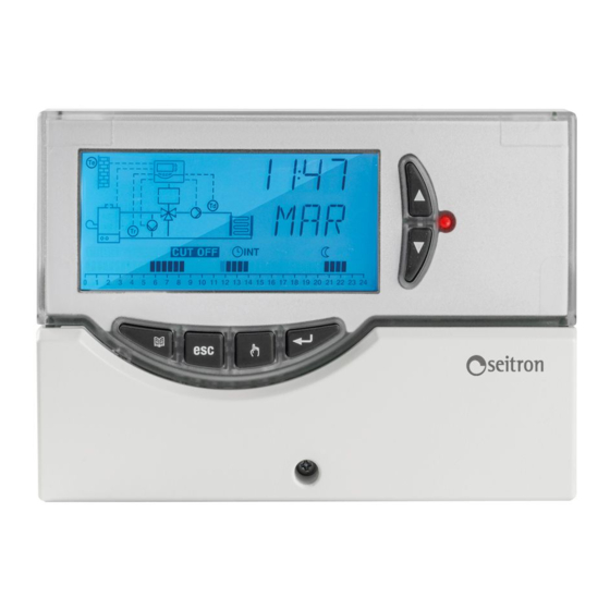
- Page 21 ──────────────────────────── DISPLAY INFORMATION The following image shows the display with all the START-UP segments on: ──────────────────────────── DESCRIPTION OF CONTROLS SELECTION KEYS Display hydraulic diagram: Probe icon. Icon on: probe present Ta Te Icon + symbol ' ' flashing: probe faulty or Td Tr not connected (if required as Te and Td) Icon off: probe not present...
- Page 22 DISPLAY TEMPERATURE / CLOCK This function aims to restore the servo motor in safety The unit is able to show on the alphanumeric display position (closing and consequently a lowering of the the current time and date and the temperatures detected supply temperature).
- Page 23 Using installer parameters ──────────────────────────── INSTALLER PARAMETERS ┌──────────────────────────────────────┐ │ ONCE THE CORRECT PASSWORD HAS BEEN │ ──────────────────────────── │ ENTERED, THE FIRST INSTALLER │ │ PARAMETER IS DISPLAYED │ Enter password └──────────────────────────────────────┘ To access the installer parameters, proceed as follows: ┌──────────────────────────────────────┐ ┌──────────────────────────────────────┐...
- Page 24 ┌──────────────────────────────────────┐ "P1 SCH" │WAIT 20 SECONDS OR PRESS THE ‘esc’ KEY│ SELECT SYSTEM TYPE │ TO EXIT INSTALLER MODE. │ └──────────────────────────────────────┘ With this parameter you can select the type of hydraulic system to be made. The unit offers the opportunity to select four different hydraulic diagrams.
- Page 25 ┌─────────────────────────────────────┐ "P2 DAT" │ MAXIMUM TEMPERATURE OF │ SYSTEM DATA SETTINGS │ SUPPLY WATER │ │—————————————————————————————————————│ With this parameter you can set all the data that │ Data │ Adjustment range │ Default │ influence the management of the hydraulic system. │——————│————————————————————│—————————│...
- Page 26 ┌─────────────────────────────────────┐ "P3 OAF" │ MINIMUM IGNITION BURNER 1 │ SETTING ANTI-FREEZE TEMPERATURE │—————————————————————————————————————│ │ Data │ Adjustment range │ Default │ This parameter allows you to set the anti-freeze │——————│————————————————————│—————————│ temperature to protect the system if the supply water │ tb1 │...
- Page 27 "P4 OAC" "P5 OCO" S E T T I N G A N T I - C O N D E N S A T I O N SETTING CUT-OFF TEMPERATURE TEMPERATURE REFERRED TO THE EXTERNAL PROBE This parameter allows you to control the temperature This parameter, if enabled, allows for the system to be detected by the probe "Tr"...
- Page 28 "P6 OFS" "P7 PMP" SETTING OFFSET OF THE PROBES CIRCULATION PUMP CONTROL With this parameter it is possible to change the By the setting of the parameter "P7 PMP", the unit temperature detected by the connected probes, by controls the activation of the circulation pump according ±5°C, so as to correct any systematic reading errors.
- Page 29 - Selecting the option H24 the circulation pump is ──────────────────────────── always active. USER PARAMETERS - Selecting the option ECO (the Ta room temperature ──────────────────────────── probe connection to the unit is compulsory) the circulation pump will be active at the following The functions that can be accessed by the user are limited and do not allow for the configuration of data that conditions:...
- Page 30 - 'Pr-1': Automatic Comfort-Economy mode (depending "U1 SFM" - Selecting the Mode of Operation on the parameter 'U3 PRG'). This parameter allows you to select the mode of operation of the unit: Display during normal operation ┌──────────────────────────────────────┐ In the comfort time slots the unit will adjust the │AFTER SELECTING THE PARAMETER 'U1 SFM'│...
- Page 31 ┌──────────────────────────────────────┐ "U2 MDY" │ USING THE ARROWS '▼' AND '▲' │ Date and time settings │ YOU CAN SET THE YEAR (1..99). │ └──────────────────────────────────────┘ This parameter allows you to adjust the date and time. ┌──────────────────────────────────────┐ │ PRESS THE ' ' KEY;...
- Page 32 "U3 PRG" Note: Below are the possible programs to modify associated to the four combinations of days available: Setting the timer G-1 => 2 programs P_1: Monday .. Friday This parameter, accessible only if the parameter 'U1' is P_2: Saturday .. Sunday set to 'Pr-1' or to 'Pr-2', allows you to set the timer.
- Page 33 Default timer RAPID INSTRUCTIONS TO SET THE TIMER To facilitate the programming operations, the unit is Note: preset as follows: In order to proceed with the timer settings, it is necessary that the user parameter " U1 SFM " is set to Combination of days: Monday ..
- Page 34 "U4 TCR" "U5 LNG" - Language settings Comfort and Economy temperature settings This parameter allows you to set the desired language, Italian or English, for the days of the calendar. This parameter allows you to set the desired Comfort and Economy temperature. ┌──────────────────────────────────────┐...
- Page 35 ──────────────────────────── TROUBLESHOOTING ──────────────────────────── The unit is able to display and, if necessary, manage any faults or alarms that are detected during operation. ──────────────────────────── ──────────────────────────── Problem Problem The password has been forgotten. The heating does not start at the set time. Solution Solution Ask the manufacturer.
Need help?
Do you have a question about the RKP01M and is the answer not in the manual?
Questions and answers