Subscribe to Our Youtube Channel
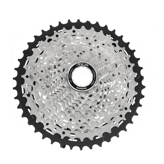
Summary of Contents for MTB SLX CS-M7000-11
- Page 1 DM-MBCS001-04 (English) Dealer's Manual ROAD Trekking City Touring/ URBAN SPORT E-BIKE Comfort Bike Cassette Sprocket CS-M7000-11 DEORE CS-M5100-11 CS-M4100-10 CS-LG600-11 CS-LG600-10 CS-HG500-10...
-
Page 2: Table Of Contents
Contents Contents ...................2 IMPORTANT NOTICE ..............3 TO ENSURE SAFETY ..............4 List of tools to be used ............6 Installation/removal ..............7 Installing the cassette sprocket .............7 Removing the cassette sprocket ............8 Sprocket pattern ..................9 • CS-M7000-11 ..........................9 • CS-M5100-11 ........................... 10 •... -
Page 3: Important Notice
IMPORTANT NOTICE IMPORTANT NOTICE • This dealer's manual is intended primarily for use by professional bicycle mechanics. Users who are not professionally trained for bicycle assembly should not attempt to install the components themselves using the dealer's manuals. If any part of the information on the manual is unclear to you, do not proceed with the installation. -
Page 4: To Ensure Safety
TO ENSURE SAFETY TO ENSURE SAFETY WARNING • Be sure to follow the instructions provided in the manuals when installing the product. Only use SHIMANO genuine parts. If a component or replacement part is incorrectly assembled or adjusted, it can lead to component failure and cause the rider to lose control and crash. - Page 5 TO ENSURE SAFETY • Always be sure to use the sprocket set bearing the same Group mark group marks of gears; never use in combination with a sprocket bearing a different group mark of gears. * Depending on the tooth combination, some may not have a mark.
-
Page 6: List Of Tools To Be Used
List of tools to be used List of tools to be used The following tools are needed for installation/removal, adjustment, and maintenance purposes. Tool TL-LR10 / TL-LR15 TL-SR23 / TL-SR24 Adjustable wrench... -
Page 7: Installation/Removal
Installation/removal Installing the cassette sprocket Installation/removal Installing the cassette sprocket Place all of the sprockets on the freewheel body. Place the sprockets in descending order from the largest sprocket. Place the sprockets so that the wide convex section of the sprocket is aligned with the wide groove in the freewheel body. -
Page 8: Removing The Cassette Sprocket
Installation/removal Removing the cassette sprocket Removing the cassette sprocket Remove the lock ring with a SHIMANO original tool. Install TL-SR23/TL-SR24 on the sprocket outward from the middle sprocket to secure the assembly. If the TL-SR23/TL-SR24 is set on a sprocket inward from the middle sprocket, it will not be stable. -
Page 9: Sprocket Pattern
Installation/removal Sprocket pattern Sprocket pattern CS-M7000-11 < 11-40T (bs), 11-42T (bt), 11-46T > Sprocket spacer Lock ring 11-40T 11-42T 11-46T Chainrings Chainrings Chainrings Number of Number of Number of teeth teeth teeth 40T bs, 11S 40B, 42T bt, 11S 42A, 46T bu, 11S 46A, 35T bs,... -
Page 10: Cs-M5100-11
Installation/removal Sprocket pattern CS-M5100-11 < 11-51T > < 11-42T > Lock ring Lock ring Sprocket spacer Sprocket spacer 11-51T 11-42T Number of teeth Mark Number of teeth Mark 51C, 42B, 45G, 11S 37A, 39C, 11S 32B, 33B, 11S 28D, 11S 24D 24T bv 11S 21H 11S 19H... -
Page 11: Cs-Lg600-11
Installation/removal Sprocket pattern CS-LG600-11 < 11-50T > Lock ring 11-50T Number of teeth Mark 50T, 43T, 36T, 30T, 26T, 23T, 20T,... -
Page 12: Cs-M4100-10
Installation/removal Sprocket pattern CS-M4100-10 < 11-46T > Lock ring 11-46T 11-42T Number of teeth Mark Number of teeth Mark 46B, 42C, 37T bv, 37T bv, 32T2 bv, 32T2 bv, 28T2 bv, 28T2 bv, 24T bv, 24T bv, 21T2 bv, 21T2 bv, 18T2 bv, 18T2 bv, 15T bj bk bv... -
Page 13: Cs-Lg600-10
Installation/removal Sprocket pattern CS-LG600-10 < 11-43T > Lock ring 11-43T Number of teeth Mark 43T, 36T, 30T, 26T, 23T, 20T,... -
Page 14: Cs-Hg500-10
Installation/removal Sprocket pattern CS-HG500-10 < 11-32T(bl), 11-34T(bj), 11-42T(bv) > < 11-25T > < 12-28T > Lock ring Lock ring Lock ring 11-25T 12-28T 11-32T(bl) Number of Mark Number of Mark Number of Mark teeth teeth teeth 25T2, 28T, 32T bl, 23T, 25T, 28T bl,... - Page 15 Please note: specifications are subject to change for improvement without notice. (English) © Feb. 2021 by SHIMANO INC. ITP...


Need help?
Do you have a question about the SLX CS-M7000-11 and is the answer not in the manual?
Questions and answers