Table of Contents
Advertisement
Quick Links
Advertisement
Table of Contents

Related Manuals for CTI GG-VL2-NH3

Summary of Contents for CTI GG-VL2-NH3
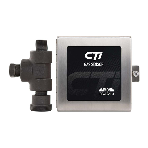
- Page 1 GG-VL2-NH3 AMMONIA VENT LINE SENSOR Installation and Operation Manual...
- Page 2 GG-VL2-NH3 Warning Use this product only in the manner described in this manual. If the equipment is used in a manner not specified by Calibration Technologies, the protection provided by the equipment may be impaired. This equipment should be installed by qualified personnel.
-
Page 3: Table Of Contents
GG-VL2-NH3 Table of Contents General description ........4 Installation ............4 Locating the sensor ........4 Installation guidelines ......... 5 Wiring ............6 Operation ............7 Start-up ............7 Calibration ........... 7 Maintenance ........... 10 Troubleshooting ..........11 Specifications ..........11 Warranty ............ -
Page 4: General Description
General Description Installation Locating the sensor The GG-VL2-NH3 sensor is a +24 VDC, three-wire, 4/20 mA sensor for ammonia. It provides an industry Note: The ½” nipple of the supplied mounting kit standard linear 4/20 mA output signal compatible with should be welded to the relief header to allow airflow most gas detection systems and PLCs. -
Page 5: Installation Guidelines
GG-VL2-NH3 Installation Guidelines: • Always assume system could discharge at any moment. Stay clear of discharge path and have escape route planned. • Make sure ammonia does not discharge onto sensor assembly or personnel working on sensor (i.e. mount sensor opposite side of discharge). -
Page 6: Wiring
GG-VL2-NH3 Wiring Electrical wiring must comply with all applicable codes. Electrical Power: 24 VDC regulated, 80 mA. Output: Linear 4/20 mA output. Monitoring equipment may have a maximum input impedance of 700 ohms. Cable Recommendation: 20/3 shielded cable (General Cable C2525A or equivalent). Length of cable to sensor should be no greater than 1,500 feet. -
Page 7: Operation
LED is not flashing. The GG-VL2-NH3 is designed with a unique safety • Adjust the zero pot until the sensor outputs 40 signal latching feature. When the signal reaches 1% mVdc from Test [-] to Test [+] (see Figure 3). - Page 8 GG-VL2-NH3 Span Calibration: Do not adjust the span pot sensor following the Zero Calibration procedure on without certified calibration gas! If span adjustment is the previous page. required, use the following procedure (see Figure 3): 4mA adjustment: Sometimes a fine adjustment of the •...
- Page 9 GG-VL2-NH3 Sensor element assembly Calibration port Unscrew cap to apply calibration gas Calibration switch Sensor cable plug Push to enter cal mode 40-200 mV mVDC Black Figure 3: Transmitter and sensor assembly...
-
Page 10: Maintenance
GG-VL2-NH3 Maintenance Sensor Replacement: (part #: GG-VL2-NH3-RS) When the sensor becomes faulty, a replacement The GG-VL2-NH3 was designed for long life and sensor element can be obtained from Calibration minimal maintenance. For proper operation it is Technologies. essential that the calibration schedule be adhered to. -
Page 11: Troubleshooting
GG-VL2-NH3 Specifications Troubleshooting Sensor Fault: (0.5 mA signal output) Input Power: +24 VDC, 80 mA Indications: (any or all) Detection Principle: Catalytic bead • Red LED on transmitter lit and voltage signal at Detection Method: Diffusion Gas: Ammonia (NH3) testpoints is 5 mVdc (.5 mA output). -
Page 12: Warranty
No goods shall be returned to CTI until receipt by the buyer of shipping instructions from CTI; and c) the right of CTI to require that the buyer provide proof of purchase such as the original invoice, bill of sale or packing slip to establish that the product is within the warranty period. - Page 13 GG-VL2-NH3...
- Page 14 GG-VL2-NH3...
- Page 15 GG-VL2-NH3...
- Page 16 GG-VL2-DOC1-4 20180808 ctiengineering.com | 866-394-5861...
Need help?
Do you have a question about the GG-VL2-NH3 and is the answer not in the manual?
Questions and answers