Table of Contents
Advertisement
Available languages
Available languages
GARAGE DOOR OPENER
Models PD210C -1/2 HP
PD212C -1/2 HP
For Residential Use Only
Owner's Manual
I
Please read this manual and the enclosed safety materials carefully!
I
Fasten the manual near the garage door after installation.
I
The door WILL NOT CLOSE unless the Protector System
and properly aligned.
I
Periodic checks of the opener are required to ensure safe operation.
I
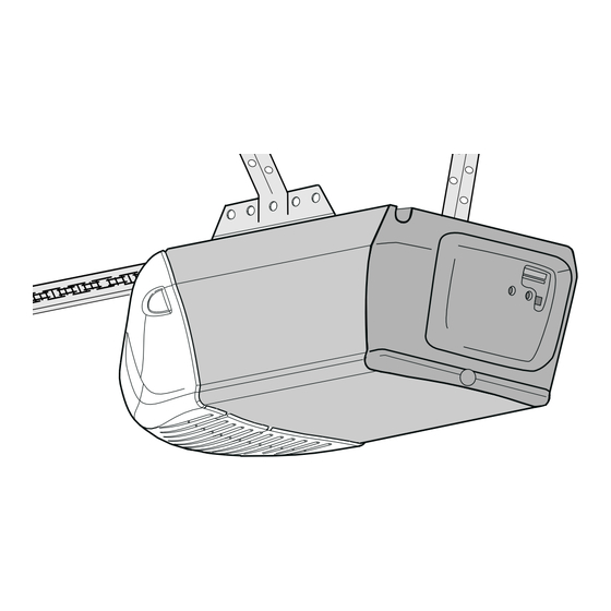
The model number label is located on the front end panel of your opener.
™
®
is connected
The Chamberlain Group, Inc.
845 Larch Avenue
Elmhurst, Illinois 60126-1196
www.chamberlaingroup.com
®
Advertisement
Chapters
Table of Contents

Related Manuals for Chamberlain Power Drive Security+ PD210C


Summary of Contents for Chamberlain Power Drive Security+ PD210C
- Page 1 GARAGE DOOR OPENER Models PD210C -1/2 HP PD212C -1/2 HP For Residential Use Only Owner’s Manual Please read this manual and the enclosed safety materials carefully! Fasten the manual near the garage door after installation. The door WILL NOT CLOSE unless the Protector System and properly aligned.
-
Page 2: Table Of Contents
TABLE OF CONTENTS Introduction Safety symbol and signal word review...2 Preparing your garage door ...3 Tools needed ...3 Planning ...4-5 Carton inventory ...6 Hardware inventory ...7 Assembly Assemble T-rail & attach the pulley bracket...8 Install the trolley ...9 Fasten the T-rail to the motor unit ...9 Install the chain/cable and sprocket cover ...10 Tighten the chain and cable ...11 Installation... -
Page 3: Preparing Your Garage Door
Preparing your garage door Before you begin: • Disable locks. • Remove any ropes connected to garage door. • Complete the following test to make sure your garage door is balanced and is not sticking or binding: 1. Lift the door about halfway as shown. Release the door. -
Page 4: Planning
Planning Identify the type and height of your garage door. Survey your garage area to see if any of the conditions below apply to your installation. Additional materials may be required. You may find it helpful to refer back to this page and the accompanying illustrations as you proceed with the installation of your opener. -
Page 5: Planning
Planning (Continued) ONE-PIECE DOOR INSTALLATIONS • Generally, a one-piece door does not require reinforcement. If your door is lightweight, refer to the information relating to sectional doors in Installation Step 11. • Depending on your door’s construction, you may need additional mounting hardware for the door bracket (Step 11). -
Page 6: Carton Inventory
Door Control Panel Rail Brace (3) 2-Conductor Bell Wire White & White/Red Trolley Chain and Cable in Dispensing Carton Safety Sensor Bracket (2) Model PD210C (1) Model PD212C (2) SECURITY✚ Single-Function Remote Control Transmitter Cable Pulley Bracket T-rail End Section (2) -
Page 7: Hardware Inventory
Hardware Inventory Separate all hardware and group as shown below for the assembly and installation procedures. Washered Bolt 5/16"-18x1/2" (2) (mounted in opener) Trolley Threaded Shaft (1) Lag Screw 5/16"-9 x1-5/8" (2) Lag Screw 5/16"-18x1-7/8" (2) Self-Threading Screw 1/4"-14x5/8" (2) Carriage Bolts 1/4"-20x1/2"... -
Page 8: Assembly Step
ASSEMBLY STEP 1 Assemble the T-Rail and Attach the Cable Pulley Bracket To avoid installation difficulties, do not run the garage door opener until instructed to do so. 1. Align the four T-rail sections on a flat surface exactly as shown. Center sections are interchangeable. -
Page 9: Install The Trolley
ASSEMBLY STEP 2 Install the Trolley • Attach the trolley threaded shaft to the trolley with the lock washer and nuts as shown. • As a temporary stop, insert a screwdriver into the hole in the front end of the T-rail. •... -
Page 10: Install The Chain/Cable And Attach The Sprocket Cover
ASSEMBLY STEP 4 Install the Chain/Cable and Attach the Sprocket Cover INSTALLING THE CHAIN/CABLE 1. Pull the cable loop from the carton and fasten it to the trolley with a master link from the hardware bag. (See Figure 1) Keep Chain & Cable •... -
Page 11: Installation
ASSEMBLY STEP 5 Tighten the Chain and Cable • Spin the inner nut and lock washer down the trolley threaded shaft, away from the trolley. • To tighten the chain, turn outer nut in the direction shown. AS YOU TURN THE NUT, KEEP THE CHAIN FROM TWISTING. -
Page 12: Installation Step
INSTALLATION STEP 1 Determine the Header Bracket Location WARNING To prevent possible SERIOUS INJURY or DEATH: • Header bracket MUST be RIGIDLY fastened to CAUTION structural support on header wall or ceiling, otherwise garage door might not reverse when required. DO NOT install header bracket over drywall. - Page 13 ONE-PIECE DOOR WITHOUT TRACK 1. Close the door and mark the inside vertical centerline of your garage door. Extend the line onto the header wall above door, as shown. If headroom clearance is minimal, you can install the header bracket on the ceiling. See page 14. If you need to install the header bracket on a 2x4 (on wall or ceiling), use lag screws (not provided) to securely fasten the 2x4 to structural supports...
-
Page 14: Install The Header Bracket
INSTALLATION STEP 2 Install the Header Bracket You can attach the header bracket either to the wall above the garage door, or to the ceiling. Follow the instructions which will work best for your particular requirements. Do not install the header bracket over drywall. -
Page 15: Attach The T-Rail To The Header Bracket
Header Wall Header Bracket Cable Pulley Bracket T-rail Garage Door HARDWARE SHOWN ACTUAL SIZE Clevis Pin 5/16" x 2-3/4" INSTALLATION STEP 3 Attach the T-Rail to the Header Bracket • Position the opener on the garage floor below the header bracket. Use packing material as a protective base. -
Page 16: Avertissement Attention
INSTALLATION STEP 4 Position the Opener Follow instructions which apply to your door type as illustrated. SECTIONAL DOOR OR ONE-PIECE DOOR WITH TRACK A 2x4 laid flat is convenient for setting an ideal door- to-T-rail distance. • Raise the opener onto a stepladder. You will need help at this point if the ladder is not tall enough. -
Page 17: Hang The Opener
INSTALLATION STEP 5 Hang the Opener Two representative installations are shown. Yours may be different. Hanging brackets should be angled (Figure 1) to provide rigid support. On finished ceilings (Figure 2), attach a sturdy metal bracket to structural supports before installing the opener. This bracket and fastening hardware are not provided. -
Page 18: Install The Door Control
CAUTION INSTALLATION STEP 6 Install the Door Control Locate door control within sight of the door at a minimum height of 5 feet where small children cannot reach, and away from moving parts of the door and door hardware. The installation surface must be smooth and flat. -
Page 19: Install The Lights
INSTALLATION STEP 7 Install the Lights • Press the release tabs on both sides of lens. Gently rotate lens back and downward until the lens hinge is in the fully open position. Do not remove the lens. • Install up to a 100 watt maximum light bulb in the socket. -
Page 20: Avertissement Attention
WARNING INSTALLATION STEP 9 Electrical Requirements CAUTION To avoid installation difficulties, do not run the opener at this time. To reduce the risk of electric shock, your garage door opener has a grounding type plug with a third grounding pin. This plug will only fit into a grounding type outlet. -
Page 21: Install The Protector System
INSTALLATION STEP 10 Install The Protector System ®... -
Page 24: Fasten The Door Bracket
INSTALLATION STEP 11 Fasten the Door Bracket... - Page 26 INSTALLATION STEP 12 Connect Door Arm to Trolley...
-
Page 28: Adjustment
ADJUSTMENT STEP 1 Adjust the UP and DOWN Travel Limits... -
Page 29: Adjust The Force
ADJUSTMENT STEP 2 Adjust the Force... -
Page 30: Adjustment
ADJUSTMENT STEP 3 Test the Safety Reversal System ADJUSTMENT STEP 4 Test the Protector System ®... -
Page 31: Operation
OPERATION IMPORTANT SAFETY INSTRUCTIONS To reduce the risk of severe injury or death: 1. READ AND FOLLOW ALL WARNINGS AND INSTRUCTIONS. 2. ALWAYS keep remote controls out of reach of children. NEVER permit children to operate or play with garage door control push buttons or remote controls. -
Page 32: Using The Wall-Mounted Door Control
Using the Wall-Mounted Door Control THE MULTI-FUNCTION DOOR CONTROL Press the push bar to open or close the door. Press again to reverse the door during the closing cycle or to stop the door while it's opening. Light feature Press the Light button to turn the opener light on or off. -
Page 33: Care Of Your Opener
Care of Your Opener LIMIT AND FORCE ADJUSTMENTS: Weather conditions may cause some minor changes in door operation requiring some readjustments, particularly during the first year of operation. Pages 28 and 29 refer to the limit and force adjustments. Only a screwdriver is required. Follow the instructions carefully. - Page 34 Having a Problem? (Continued) 6. The garage door opens and closes by itself: • Be sure that all remote control push buttons are off. • Remove the bell wire from the door control terminals and operate from the remote only. If this solves the problem, the door control is faulty (replace), or there is an intermittent short on the wire between the door control and the motor unit.
-
Page 35: Programming
PROGRAMMING Your garage door opener has already been programmed at the factory to operate with your hand-held remote control. The door will open and close when you press the large push button. Below are instructions for programming your opener to operate with additional Security To Add an Additional Hand-held Remote Control USING THE “LEARN”... -
Page 36: Using Multi-Function Door Control
To Add or Change a Keyless Entry PIN NOTE: Your new Keyless Entry must be programmed to operate your garage door opener. USING THE “LEARN” BUTTON 1. Press and release the “learn” button on motor unit. The learn indicator light will glow steadily for 30 seconds. -
Page 37: Repair Parts Pages
REPAIR PARTS Rail Assembly Parts Installation Parts PART 41A5273-14 Multi-function door control panel 41A5056-17 Single-function remote control, 10A20 29B137 41A2828 217A238 41A4353 41A5047 178B35 178B34 12B350 41A5034 41A5266-1 41A3475-17 Installation hardware bag (see page 7). 114A2525 PART DESCRIPTION 4A1008 Master link kit 41A3489 Complete trolley assembly 183B112... -
Page 38: Motor Unit Assembly Parts
Motor Unit Assembly Parts PART DESCRIPTION 31D380 Sprocket cover 41C4220A Gear and sprocket assembly Complete with: Spring washer, Thrust washer, Retaining ring, Bearing plate, Roll pins (2), Drive gear and worm gear, Helical gear w/retainer and grease 41A2817 Drive/worm gear kit w/grease, Roll pins (2) 41B4245 Line cord... -
Page 39: Accessories
ACCESSORIES 953C SECURITY Remote Control: Includes visor clip. SECURITY 956C Mini Remote Control: With key ring and Velcro fastening strip. 945C Multi-Function Door Control Panel: Provides a Lock feature which prevents operation of garage door opener from portable remotes and a Light feature for constant light. -
Page 40: How To Order Repair Parts
CHAMBERLAIN GARAGE DOOR OPENER ONE-YEAR LIMITED WARRANTY The Chamberlain Group, Inc. (“Seller”) warrants to the first retail purchaser of this product, for the residence in which this product is originally installed, that it will be free from any defect in materials and/or workmanship for a period of one year from the date of purchase. -
Page 41: Manuel D'instructions
OUVRE-PORTE DE GARAGE Modèles PD210C -1/2 HP PD212C -1/2 HP Pour résidences seulement Manuel d’instructions Lire attentivement ce manuel ainsi que les consignes de sécurité! Après la pose, accrocher ce manuel près de la porte de garage pour s’y reporter ultérieurement. -
Page 42: Introduction
TABLE DES MATIÈRES Introduction Revue des symboles de sécurité et des mots de signalement ..... . .2 Préparation de votre porte de garage ....3 Outils nécessaires . -
Page 43: Préparation De Votre Porte De Garage
Préparation de votre porte de garage Avant de commencer : • Inactiver les serrures. • Retirer toute corde raccordée à la porte de garage. • Procéder au contrôle suivant pour s’assurer que la porte est bien équilibrée et qu’elle ne coince pas : 1. - Page 44 Planification Identifier le type et la hauteur de votre porte de garage. Examiner la région du garage pour noter si l’une des conditions ci-après s’applique à votre installation. Des matériaux supplémentaires peuvent être nécessaires. Il vous sera peut-être utile de vous reporter à cette page et aux illustrations qui l’accompagnent en procédant à...
- Page 45 Planification (suite) POSE DE PORTE RIGIDE • En règle générale, une porte rigide ne nécessite aucun renfort. Pour une porte légère, prière de se reporter aux informations ayant trait aux portes articulées à la 11e opération de montage. • En fonction de la construction de la porte, des fixations supplémentaires seront peut-être requises pour le support de la porte.
-
Page 46: Inventaire Des Boîtes D'emballage
Les pièces peuvent être coincées dans la mousse. Les fixations nécessaires à l’assemblage et au montage apparaissent sur la page suivante. Conserver la boîte et le matériel d’emballage jusqu’au terme du montage et du réglage. Série PD210C (1) Série PD212C (2) SECURITY Télécommande à un bouton Support de la poulie du câble... -
Page 47: Inventaire Des Fixations
Inventaire des fixations Séparer toutes les fixations et les regrouper comme illustré ci-après aux fins des opérations d’assemblage et de montage. Boulon hexagonal de Boulon à rondelle de 5/16 de po-18x7/8 de po (3) 5/16 de po-1/2 po (2) (montées dans l'ouvre-porte) Tige filetée du chariot (1) Tire-fond de... -
Page 48: Montage
MONTAGE - 1 OPÉRATION Assemblage des rails et pose du support de la poulie du câble Pour ne pas rencontrer de difficultés pendant la pose, ne faire fonctionner l'ouvre-porte de garage que lorsque cela est expressément indiqué. 1. Sur une surface plane, aligner les 4 sections de rail, exactement comme il est illustré. -
Page 49: Pose Du Chariot
MONTAGE - OPÉRATION Pose du chariot • Poser la tige filetée sur le chariot avec une rondelle-frein et des écrous, comme il est illustré. • Comme butée temporaire, introduire un tournevis dans le trou qui se trouve à l'avant du rail. •... - Page 50 MONTAGE - 4 OPÉRATION Pose de la chaîne et du câble et fixation du carter du pignon POSE DE LA CHAINE ET DU CABLE 1. Tirer la boucle du câble et l'accrocher sur le chariot avec un des maillons de raccord que l'on trouvera dans le sachet des fixations.
-
Page 51: Tension De La Chaîne Et Du Cäble
MONTAGE - 5 OPÉRATION Tension de la chaîne et câble • Dévisser l’écrou intérieur de la tige filetée du chariot et éloigner la rondelle. • Pour tendre la chaîne, tourner l’écrou extérieur dans le sens illustré. ALORS QUE L’ON TOURNE L’ÉCROU, EMPÊCHER LA CHAÎNE DE VRILLER. -
Page 52: Déterminer L'emplacement Du Support De Linteau
POSE - 1 OPÉRATION Déterminer l'emplacement du support de linteau AVERTISSEMENT AVERTISSEMENT Pour prévenir d’éventuelles BLESSURES GRAVES ou la MORT : • Le support de linteau DOIT être fixé DE MANIÈRE RIGIDE à la ATTENTION solive sur le linteau ou le plafond, sinon la porte de garage pourrait ne pas remonter au besoin. - Page 53 PORTE RIGIDE SANS GUIDES 1. La porte étant fermée, repérer et tracer l'axe vertical de la porte du garage et prolonger cette ligne sur le mur, au-dessus de la porte comme il est illustré. Si la hauteur au-dessus du plafond n'est pas suffisante, on pourra poser le support de linteau sur le plafond.
-
Page 54: Pose Du Support De Linteau
POSE - 2 OPÉRATION Pose du support de linteau Le support de linteau peut être fixé soit sur le mur au- dessus de la porte, soit sur le plafond. Suivre les instructions qui répondent le mieux aux besoins particuliers. Ne pas poser le support de linteau sur des plaques de placoplâtre. -
Page 55: Fixation Du Rail Sur Le Support De Linteau
Linteau Support de linteau Support de la poulie de câble Rail Porte de garage GRANDEUR RÉELLE DES FIXATIONS Axe de chape de 5/16 po x 2-3/4 po POSE - 3 OPÉRATION Fixation du rail sur le support de linteau • Positionner l'ouvre-porte de garage sur le plancher, juste sous le support de linteau. -
Page 56: Positionnement De L'ouvre-Porte
POSE - 4 OPÉRATION Positionnement de l'ouvre-porte Suivre les instructions qui se rapportent à la porte du garage, en se rapportant aux illustrations. PORTE ARTICULÉE OU PORTE RIGIDE AVEC GUIDES Un 2x4 convient très bien pour obtenir l'espace qu'il faut entre la porte et le rail. -
Page 57: Accrochage De L'ouvre-Porte
POSE - 5 OPÉRATION Accrochage de l'ouvre-porte Les illustrations représentent deux poses type. La pose peut toutefois être différente. Les supports de suspension doivent être inclinés, Figure 1, pour assurer un support rigide. Dans le cas d'un plafond fini, (Figure 2), fixer une cornière aux solives du plafond avant de poser l'ouvre- porte. -
Page 58: Pose De La Commande De Porte
AVERTISSEMENT POSE - 6 OPÉRATION Pose de la commande de porte ATTENTION Poser la commande murale dans un endroit où on pourra la voir de la porte, à au moins 5 pieds du sol, là où les enfants ne pourront pas l'atteindre et loin de toutes les pièces mobiles et fixations de la porte. -
Page 59: Pose Des Ampoules
POSE - 7 OPÉRATION Pose des ampoules • Appuyer sur les pattes de dégagement des deux côtés du diffuseur. Faire délicatement tourner le diffuseur vers l’arrière et le bas jusqu’à ce que la charnière du diffuseur soit en position complètement ouverte. Ne pas retirer le diffuseur. -
Page 60: Exigences Électriques
AVERTISSEMENT POSE - 9 OPÉRATION Exigences électriques ATTENTION Pour éviter de rencontrer des difficultés pendant la pose, ne pas faire fonctionner l'ouvre-porte pour le moment. Afin de minimiser les risques de chocs électriques, le cordon d'alimentation de l'ouvre-porte de garage comporte une fiche à... -
Page 61: Pose Du Système Protector
POSE - 10 OPÉRATION Pose du Système Protector AVERTISSEMENT AVERTISSEMENT ® ATTENTION... - Page 62 MONTAGE SUR GUIDES DE PORTE (côté droit) MONTAGE MURAL (côté droit) MONTAGE AU SOL (côté droit)
- Page 63 Plafond fini...
-
Page 64: Fixation Du Support De La Porte
POSE - 11 OPÉRATION Fixation du support de porte ATTENTION DES RENFORTS HORIZONTAUX ET VERTICAUX SONT REQUIS DANS LE CAS D'UNE PORTE DE GARAGE LÉGÈRE (EN FIBRE DE VERRE, EN ALUMINIUM, EN ACIER, EN PANNEAUX DE VERRE, ETC.). (NON FOURNIS) - Page 65 Plafond fini PORTE MÉTALLIQUE DES RENFORTS HORIZONTAUX ET VERTICAUX SONT REQUIS DANS LE CAS D'UNE PORTE DE GARAGE LÉGÈRE (EN FIBRE DE VERRE, EN ALUMINIUM, EN ACIER, EN PANNEAUX DE VERRE, ETC.). (NON FOURNIS) PORTE EN BOIS...
- Page 66 POSE - 12E OPÉRATION Fixation de la biellette au chariot...
-
Page 68: Réglage Des Courses
RÉGLAGES - 1 OPÉRATION Réglage des courses d’ouverture et de fermeture AVERTISSEMENT AVERTISSEMENT WARNING ATTENTION CAUTION AVERTISSEMENT ATTENTION 2-4"... -
Page 69: Réglage De La Force
RÉGLAGES - 2 OPÉRATION Réglage de la force AVERTISSEMENT AVERTISSEMENT ATTENTION... - Page 70 RÉGLAGES - 3 OPÉRATION Essai du système d’inversion de sécurité RÉGLAGES - 4 OPÉRATION Essayer le système de protection AVERTISSEMENT AVERTISSEMENT ATTENTION WARNING CAUTION AVERTISSEMENT AVERTISSEMENT ATTENTION...
-
Page 71: Fonctionnement
FONCTIONNEMENT IMPORTANTES CONSIGNES DE SÉCURITÉ Pour réduire le risque de blessures graves ou de mort : 1. LIRE ET SUIVRE TOUS LES AVERTISSEMENTS ET INSTRUCTIONS. 2. TOUJOURS garder les télécommandes hors de la portée des enfants. Ne JAMAIS laisser les enfants faire fonctionner les télécommandes ou les boutons-poussoirs de la commande de porte ou jouer avec ceux-ci. -
Page 72: Utilisation De La Commande De Porte À Montage Mural
Utilisation de la commande de porte à montage mural PANNEAU COMMANDE DE PORTE Appuyer sur la barre pour ouvrir ou fermer la porte. Appuyer à nouveau pour faire remonter la porte lors du cycle de fermeture ou pour arrêter la porte pendant le cycle d'ouverture. -
Page 73: Entretien De Votre Ouvre-Porte De Garage
Entretien de l’ouvre-porte de garage RÉGLAGES DE COURSE ET DE FORCE : Les conditions climatiques risquent de causer de petites modifications dans le fonctionnement de la porte qui devra alors être réglée, en COMMANDES DE COURSE particulier après la première année d’utilisation. - Page 74 Défauts de fonctionnement (suite) 6. La porte s’ouvre et se ferme toute seule: • S’assurer que tous les boutons-poussoirs de la télécommande sont à la position d’arrêt. • Débrancher le fil de sonnerie des bornes de la commande de porte et faire fonctionner la télécommande seulement. Si ceci résout le problème, la commande de porte est défectueuse (il faudra alors la remplacer) ou il y a un court- circuit intermittent sur le fil entre la commande de porte et le...
-
Page 75: Pour Ajouter Une Télécommande À Main
PROGRAMMATION L’ouvre-porte de garage a été programmé en usine de manière à fonctionner avec la télécommande à main fournie. La porte s’ouvrira et se fermera lorsqu’on appuie sur le gros bouton-poussoir. Ci-après se trouvent des instructions pour programmer votre ouvre-porte en vue du fonctionnement avec d’autres télécommandes Security . -
Page 76: Pour Ajouter Ou Modifier Un Nip D'entrée Sans Clé
Pour ajouter ou modifier un NIP d’entrée sans clé REMARQUE : Votre nouvelle entrée sans clé doit être programmée de manière à faire fonctionner votre ouvre-porte de garage. UTILISATION DU BOUTON LEARN 1. Enfoncer et tenir le bouton LEARN sur le moteur. Le témoin lumineux LEARN s’allumera en continu pendant 30 secondes. -
Page 77: Pièces De Rechange
PIÈCES DE RECHANGE Pièces d’assemblage des rails Pièces pour la pose RÉF. N° DE RÉF. PIÈCE 41A5273-14 41A5056-17 10A20 29B137 41A2828 217A238 41A4353 41A5047 178B35 178B34 12B350 41A5034 41A5266-1 41A3475-17 114A2525 N° DE PIÈCE DÉSIGNATION 4A1008 Maillon de raccord 41A3489 Chariot complet 183B112 Support (chacune) - Page 78 Pièces du bloc-moteur N° DE RÉF. PIÈCE DÉSIGNATION 31D380 Carter du pignon 41C4220A Pignon et engrenage Comprend: Rondelle-frein Rondelle de butée Jonc d’arrêt Plaque de butée Goupille cylindrique (2) Pignon menant et vis sans fin Pignon hélicoïdal avec flasque et graisse 41A2817 Vis sans fin/pignon menant avec graisse...
-
Page 79: Accessoires
ACCESSOIRES 953C Télécommande à fonctions multiples SECURITY : Comprend agrafe de pare-soleil. Mini-télécommande à fonctions 956C multiples SECURITY : avec porte-clé et ruban d’attache en Velcro. 945C Panneau commande de porte à trois boutons : La caractéristique de verrouillage est conçue pour empêcher le fonctionnement de la porte à... -
Page 80: Comment Commander Des Pièces De Rechange
GARANTIE LIMITÉE D’UN AN SUR L'OUVRE-PORTE DE GARAGE CHAMBERLAIN Chamberlain/Garaga («vendeur») garantit, au premier acheteur de détail de ce produit, pour la résidence dans laquelle ce produit a été installé à l’origine, qu’il sera exempt de vices de matériaux et/ou d’exécution pendant un délai d’un an depuis la date d’achat. Le produit doit être utilisé...
Need help?
Do you have a question about the Power Drive Security+ PD210C and is the answer not in the manual?
Questions and answers
Good day folks: The wall mounted door opener light is not working on my model PD210 opener. Is there a bulb inside I can replace. I have not opened it up yet to see if I can. Any help would be appreciated. Thank you, Paul Smith