Table of Contents
Advertisement
Quick Links
Purchase Date
Questions, problems, missing parts? Before returning to your retailer, call our customer
service department at 1-800-527-1292, 8:30 a.m. - 5 p.m., CST, Monday - Friday.
ATTACH YOUR RECEIPT HERE
1
ITEM #2742219
2742222
2742220
2742221
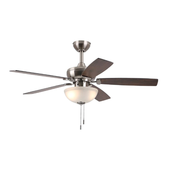
SD44 LED
CEILING FAN
MODEL #SD44BNK5LS
SD44LW5LS
SD44MBK5LS
SD44NWZ5LS
Español p. 20
ADJUNTE SU RECIBO AQUÍ
4007498
Advertisement
Table of Contents

Related Manuals for Energy Star SD44BNK5LS


Summary of Contents for Energy Star SD44BNK5LS
- Page 1 ITEM #2742219 2742222 2742220 2742221 SD44 LED CEILING FAN MODEL #SD44BNK5LS SD44LW5LS SD44MBK5LS SD44NWZ5LS Español p. 20 ATTACH YOUR RECEIPT HERE ADJUNTE SU RECIBO AQUÍ 4007498 Purchase Date Questions, problems, missing parts? Before returning to your retailer, call our customer...
-
Page 2: Table Of Contents
TABLE OF CONTENTS Safety Information ......................... 2 Package Contents ......................... 5 Hardware Contents ....................... 6 Preparation ........................... 6 Initial Installation ........................6 Downrod-Style Fan Mounting ....................8 Closemount-Style Fan Mounting ..................10 Wiring ..........................11 Final Installation ........................13 Operating Instructions ......................16 Care and Maintenance ...................... - Page 3 SAFETY INFORMATION READ AND SAVE THESE INSTRUCTIONS Please read and understand this entire manual before attempting to assemble, install or operate the product. • Do not discard fan carton or foam inserts. Should this fan need to be returned to the factory for repairs, it must be shipped in its original packaging to ensure proper protection against damage that might exceed the initial cause for return.
- Page 4 SAFETY INFORMATION WARNING WARNING To reduce the risk of fire or electrical shock, do not use the fan with any solid state speed control device or control fan speed with a full range dimmer switch. To reduce the risk of fire, electrical shock or personal injury, do not bend the blade arms when installing them, balancing the blades or cleaning the fan.
-
Page 5: Package Contents
PACKAGE CONTENTS PART DESCRIPTION PART DESCRIPTION QUANTITY QUANTITY Canopy Mounting Screw Downrod /Lock Washer Canopy (preassembled) Mounting Bracket Pin (preassembled) Motor Housing Clip (preassembled) Yoke Cover Rubber Washer Light Kit Fitter (preassembled) Blade Hex Nut (preassembled) Blade Arm Flat Washer (preassembled) Shade Bulb Motor Screw/Lock Washer... -
Page 6: Hardware Contents
HARDWARE CONTENTS (shown actual size) Fiber Blade Blade Screw Wire Washer Connector Qty. 15 Qty. 15 + 1 extra Qty. 4 Pull Chain + 1 extra Extension Qty. 2 PREPARATION Before beginning assembly of product, make sure all parts are present. Place motor on carpet or on foam to avoid damage to finish. - Page 7 INITIAL INSTALLATION 2. Determine mounting method to use. A. Downrod mount (standard or angled ceiling) B. Closemount (standard ceiling only) IMPORTANT: If using the angle mount, check to make sure the ceiling angle is not steeper than 19°. *Helpful Hint: Downrod-style mounting is best suited for ceilings 8 ft.
-
Page 8: Downrod-Style Fan Mounting
INITIAL INSTALLATION 5. Remove motor screws/lock washers (J) and from underside of motor housing (D). [If there are plastic motor blocks installed with the motor screws/lock washers (J), discard the plastic motor blocks.] For DOWNROD-STYLE FAN MOUNTING, proceed to step 1 below. Plastic Motor Block For CLOSEMOUNT-STYLE FAN MOUNTING, skip to page 10. - Page 9 DOWNROD-STYLE FAN MOUNTING Slip downrod (A) into yoke, align holes and re-install pin (L) and clip (M). Tighten downrod (A) set screws and then tighten nuts. Slide yoke cover (E) down until it rests on top of motor housing (D). Set Screw and Nut Depending on the length of downrod you use, you...
-
Page 10: Closemount-Style Fan Mounting
DOWNROD-STYLE FAN MOUNTING Install hanging ball of downrod (A) into opening of mounting bracket (C). Align the slot in hanging ball with the tab in mounting bracket (C). DANGER: Failure to align slot in hanging ball with the tab in mounting bracket (C) may result in serious injury or death. -
Page 11: Wiring
CLOSEMOUNT-STYLE FAN MOUNTING Pull wires up through hole in the middle of the Screw canopy (B) and attach canopy (B) to motor housing (D) using the three previously removed Lock screws and lock washers. Washer Temporarily hang fan on the tab on the mounting bracket (C) using one of the non-slotted holes in the canopy (B). - Page 12 WIRING Choose wiring diagram (Fig. 1a, Fig. 1b or Fig. 1c) FAN AND LIGHT CONTROLLED BY PULL CHAINS that fits your situation and make appropriate wiring connections as follows: [IMPORTANT: Use one of 120V POWER the wire connectors (CC) to make each wire FROM CEILING connection, making sure to screw wire connector BLACK (POWER)
-
Page 13: Final Installation
WIRING Wrap electrical tape (not included) around each individual wire connector (CC) down to the wire. WARNING: Make sure no bare wire or wire strands are visible after making connections. Place GREEN and WHITE wire connections on the opposite side of the outlet box from the BLACK and BLUE wire connections. - Page 14 FINAL INSTALLATION DANGER: To reduce the risk of serious bodily injury, DO NOT use power tools to assemble the blades (G). If overtightened, blades (G) may crack and break. Partially insert three blade screws (AA) along with three fiber blade washers (BB) into holes in blade (G) to attach blade arm (H) to blade (G).
- Page 15 FINAL INSTALLATION 5. Remove finial (S), finial plate (R), hex nut (O), flat washer (P) and rubber washer (N) from the threaded rod at the bottom of the light kit fitter (F). Save for later use. Threaded Install bulbs (Q). CAUTION: When replacing bulb(s), allow bulb(s) and shade (I) to cool down before touching.
-
Page 16: Operating Instructions
FINAL INSTALLATION Attach applicable pull chain extensions (DD) or custom pull chain extensions (not included) to the fan and light pull chains. Assembly is now complete. Hardware Used Pull Chain Extension (For Fan) (For Light) OPERATING INSTRUCTIONS The pull chain located on the switch housing at the top of the light kit fitter (F) has four positions to control fan speed. - Page 17 OPERATING INSTRUCTIONS Use the fan reverse switch, located on the switch housing, to optimize your fan for seasonal performance. A ceiling fan will allow you to raise your thermostat setting in summer and lower your Switch thermostat setting in winter without feeling a Housing difference in your comfort.
-
Page 18: Care And Maintenance
CARE AND MAINTENANCE At least twice each year, lower canopy (B) to check downrod (A) assembly, and then tighten all screws on fan. Clean motor housing (D) with only a soft brush or lint-free cloth to avoid scratching the finish. Clean blades (G) with a lint-free cloth. You may occasionally apply a light coat of furniture polish to wood blades for added protection. -
Page 19: Limited Lifetime Warranty
TROUBLESHOOTING PROBLEM (cont.) POSSIBLE CAUSE CORRECTIVE ACTION [Fan operates but 4. Wires in light kit fitter not wired 4. Check that male and female correctly. plugs in light kit fitter are light fails.] connected properly according to instructions on page 14. NOTE: A small amount of "wobble"...
Need help?
Do you have a question about the SD44BNK5LS and is the answer not in the manual?
Questions and answers