Table of Contents
Advertisement
Available languages
Available languages
Quick Links
Advertisement
Chapters
Table of Contents

Related Manuals for Vaillant VR 34


Summary of Contents for Vaillant VR 34
- Page 1 VR 34 DE, GB, CZ, NL...
- Page 3 Für den Fachhandwerker Installationsanleitung Schnittstelle 0-10 V VR 34...
-
Page 4: Table Of Contents
Verwendete Symbole ......3 Sicherheitshinweise und Vor schriften........4 Sicherheitshinweise .........4 Vorschriften..........4 Gerätebeschreibung ......5 Bestimmungsgemäße Verwendung ..5 CE-Kennzeichnung ........5 Anwendung ..........6 Lieferumfang ..........6 Anschlüsse ..........7 Montage ..........7 Elektrische Installation .....9 Recycling und Entsorgung ....11 Installationsanleitung Schnittstelle 0-10 V VR 34 0020017083_01... -
Page 5: Hinweise Zur Dokumentation 1
Aufbewahrung der Unterlagen Hinweis Geben Sie diese Installationsanleitung an den Nützliche Informationen und Hinwei- Anlagenbetreiber weiter. Dieser übernimmt die Aufbewahrung, damit die Anleitung bei Bedarf zur Verfügung steht. • Symbol für eine erforderliche Aktivität Installationsanleitung Schnittstelle 0-10 V VR 34 0020017083_01... -
Page 6: Sicherheitshinweise Und Vor Schriften
Heizgerät reicht nicht aus, um alle schriften der Energieversorger. Klemmen des Systems spannungsfrei Für den Anschluss der 0-10 V Schnittstelle zu schalten. sind handelsübliche Leitungen zu verwenden. Die maximale Leitungslänge zwischen VR 34 und DDC beträgt 6 m. Installationsanleitung Schnittstelle 0-10 V VR 34 0020017083_01... -
Page 7: Gerätebeschreibung 3
Gerätebeschreibung 3 Gerätebeschreibung CE-Kennzeichnung Die Schnittstelle 0-10 V VR 34 entspricht bei Bestimmungsgemäße Verwendung Berücksichtigung der Installationsvorschriften Die 0-10 V Schnittstelle VR 34 ermöglicht es, den Anforderungen der relevanten Richtlinien einen DDC-Regler an ein Vaillant eBUS-Heiz- und Normen. gerät anzuschließen. -
Page 8: Anwendung
3 Gerätebeschreibung Anwendung Sollwertsignal für das Heizgerät um. Es kann Die Schnittstelle 0-10 V VR 34 kommt zur An- auf der Klemme „F“ einen Fehler des Heizge- wendung, wenn ein vorhandener DDC räts signalisieren. Das Fehlersignal bleibt so- Fremdregler an ein Vaillant Heizgerät mit... -
Page 9: Anschlüsse
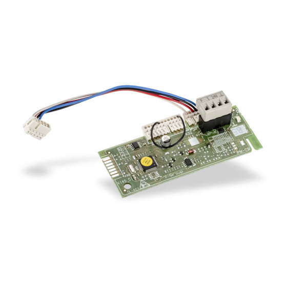
• Öffnen Sie den Schaltkasten des Heizgerä- tes gemäß der Installationsanleitung des Abb. 3.2 Anschlüsse Heizgerätes. • Verbinden Sie die 0-10 V Schnittstelle VR 34 Legende Steckplatz zum Anschluss an das Heizgerät und das Heizgerät mit dem beiliegenden 2 Anschlussklemme DDC-Regler Kabel (2). -
Page 10: Montage
Schaltkasten geführt wird. Abb. 4.2 0-10 V Schnittstellen-Platine einbauen Abb. 4.1 Busleitung an der Anschlussklemme im Heizgerät anschließen Abb. 4.3 Kabeldurchführung • Sichern Sie die 0-10 V Schnittstelle mit der beiliegenden Kabeldurchführung (4). Installationsanleitung Schnittstelle 0-10 V VR 34 0020017083_01... -
Page 11: Elektrische Installation 5
Klemmen des Systems spannungsfrei zu schalten. Abb. 5.1 Schnittstelle0-10 V anschließen • Schließen Sie den externen DDC-Regler (1) an der 0-10 V Schnittstelle VR 34 an. Beachten Sie hierbei die Polung der An- schlüsse. • Das Steuersignal von der DDC-Reglung muss an die Klemme ,,I“, die Masseleitung... - Page 12 Es ist kein DDC-Regler angeschlossen oder die Spannung ist kleiner als 0,5 V. – Schnell blinkend Es besteht keine eBUS-Verbindung zum Heizgerät. – aufblitzen Normalfunktion, Datenverkehr zwischen Abb. 5.2 LED eBUS und 0-10 V Schnittstelle. Legende Status LED Installationsanleitung Schnittstelle 0-10 V VR 34 0020017083_01...
-
Page 13: Recycling Und Entsorgung 6
Sowohl die 0-10 V Schnittstelle als auch die zugehörige Transportverpackung bestehen zum weitaus überwiegenden Teil aus recycle- fähigen Rohstoffen. Gerät Die Vaillant Schnittstelle 0-10 V VR 34 gehört nicht in den Hausmüll. Sorgen Sie dafür, dass das Altgerät einer ordnungsgemäßen Entsor- gung zugeführt wird. Verpackung Sorgen Sie dafür, dass die Verpackung einer... - Page 15 For the heating engineer Installation manual Interface 0-10 V VR 34...
- Page 16 Description of the appliance ....5 Intended use ..........5 CE labelling ..........5 Application ..........5 Scope of delivery and accessories ..6 Connections ..........6 Installation .......... 7 Electrical installation ......8 Recycling and disposal ....10 Installation manual Interface 0-10 V VR 34 0020017083_01...
-
Page 17: Notes On The Documentation 1
Please pass on this installation manual to the the product and environment! owner of the system. It is advised to store all boiler and accessory manuals together. Note Useful information and instructions! • Symbol for a necessary task Installation manual Interface 0-10 V VR 34 0020017083_01... -
Page 18: Safety Instructions And Regulations
Before working on the appliance, switch off the power supply and secure it against reconnection. Using the mains switch on the controllers is not sufficient to isolate all terminals of the system. Installation manual Interface 0-10 V VR 34 0020017083_01... -
Page 19: Description Of The Appliance 3
Management System (BEMS) with a Vaillant eBus boiler. Application The 0-10 V VR 34 interface is used to connect Hinweis BEMS equipment to a Vaillant boiler with an Beachten Sie, dass die 0-10 V eBus interface. It transfers a voltage input on Schnittstelle VR 34 nicht zur gleich- terminal “I”... -
Page 20: Scope Of Delivery And Accessories
Input voltage [V] down 24 V Abb. 3.1 Kennlinie 0-10 V Schnittstelle Note The earth terminal has ground potential. Abb. 3.1 Connections 1 Terminal for connection to boiler 2 BEMS controller terminal Installation manual Interface 0-10 V VR 34 0020017083_01... -
Page 21: Installation 4
(3) in the lower part of the Abb. 4.1 Connection of bus line to terminal electronics box, making sure the fastening clip grips the groove on the partition in the electronics box. Abb. 4.2 Installation of interface board Installation manual Interface 0-10 V VR 34 0020017083_01... - Page 22 Abb. 4.3 Cable feedthrough sufficient to isolate all terminals of • Secure the 0-10 V interface with the the system. enclosed cable cable clamp (4). Installation manual Interface 0-10 V VR 34 0020017083_01...
-
Page 23: Electrical Installation 5
Abb. 5.1 Connect interface 0-10 V Status LED - Connect the external BEMS controller (3) to the 0-10 V VR 34 interface. Take care to note the polarity of the connection. - The control signal from the BEMS controller has to be connected to terminal “I”. -
Page 24: Recycling And Disposal
Do not dispose of your Vaillant 0-10 V interface with household waste. Make sure that used devices are taken for proper disposal. Packaging Make sure that the packaging is taken for proper disposal and recycling. Installation manual Interface 0-10 V VR 34 0020017083_01... - Page 25 Pro servisního technika Návod k instalaci Rozhraní 0-10 V VR 34...
- Page 26 Předpisy ............4 Popis zařízení ........5 Použití v souladu s určením ....5 Označení CE..........5 Použití ............6 Rozsah dodávky ........6 Připojení ............. 7 Montáž ..........7 Elektrická instalace ......9 Recyklace a likvidace ....... 11 Návod k instalaci rozhraní 0-10 V VR 34 0020017083_01...
-
Page 27: Informace K Dokumentaci 1
Uložení dokumentace Upozornění Návody k montáži laskavě předejte provozo- Užitečné informace a pokyny. vateli zařízení. Ten zajistí jejich uložení tak, aby návod byl v případě potřeby k dispozici. • Symbol potřebné činnosti Návod k instalaci rozhraní 0-10 V VR 34 0020017083_01... -
Page 28: Bezpečnostní Pokyny A Předpisy
Pro připojení rozhraní 0-10 V je třeba použít Vypnutí síťového vypínače na topném běžná vedení. Maximální délka vedení mezi tělese nestačí k tomu, aby bylo na VR 34 a DDC je 6 m. všech svorkách systému odpojeno napětí. Návod k instalaci rozhraní 0-10 V VR 34 0020017083_01... -
Page 29: Popis Zařízení 3
VR 34 žádnou funkci! V tom případě odpojte regulátor pro sběrnici eBUS od zařízení. Pozor! Jakékoliv jiné použití není považováno za použití v souladu s určením a je zakázáno! Návod k instalaci rozhraní 0-10 V VR 34 0020017083_01... -
Page 30: Použití
3 Popis zařízení Použití tělesa. Chybový signál zůstane aktivní, dokud Rozhraní 0-10 V VR 34 se používá, když se má se chyba neodstraní a topné těleso se nezbaví na topné těleso Vaillant s rozhraním eBUS poruchy. připojit existující cizí regulátor. -
Page 31: Připojení
0-10 V jsou 2 Připojovací svorka regulátoru DDC označeny X31. • Namontujte rozhraní 0-10 V VR 34 (1) do ov- ládací skříňky. Zastrčte modul do vedení (3) dole v ovládací skříňce. Dbejte na to, aby zářez desky tištěných spojů... -
Page 32: Montáž
Obr. 4.3 Vedení kabelů • Zajistěte rozhraní 0-10 V přiloženou kabelo- Obr. 4.1 Připojení vedení sběrnice na připojovací vou průchodkou (4). svorku v topném tělese Obr. 4.2 Montáž desky rozhraní 0-10 V Návod k instalaci rozhraní 0-10 V VR 34 0020017083_01... -
Page 33: Elektrická Instalace 5
• Připojte externí regulátor DDC (1) na ro- zhraní 0-10 V VR 34. Dbejte na správné pólování přípojů. • Řídicí signál z regulátoru DDC musí být připojen na svorku "I", zemnicí vodič na svorku " ". Návod k instalaci rozhraní 0-10 V VR 34 0020017083_01... - Page 34 0,5 V. – Rychle bliká Topné těleso není připojeno na sběrnici eBUS. – Záblesky Normální funkce, přenos dat mezi sběrnicí Obr. 5.2 LED eBUS a rozhraním 0-10 V. Legenda Stavové LED Návod k instalaci rozhraní 0-10 V VR 34 0020017083_01...
-
Page 35: Recyklace A Likvidace 6
Rozhraní 0-10 V i příslušný přepravní obal jsou z převážné části vyrobeny z recyklovatelných surovin. Zařízení Rozhraní Vaillant 0-10 V VR 34 nepatří do do- movního odpadu. Zajistěte, aby starý přístroj byl předán k řádné likvidaci. Balení Zajistěte, aby byl obal předán k řádné... - Page 37 Voor de installateur Installatiehandleiding Interface 0-10 V VR 34...
- Page 38 ..........4 Veiligheidsaanwijzingen ......4 Voorschriften ..........4 Toestelbeschrijving ......5 Gebruik volgens de voorschriften ..5 CE-markering ..........5 Toepassing ..........6 Leveringsomvang ........6 Aansluitingen ..........7 Montage ..........7 Elektrische installatie .......9 Recycling en afvoer ......11 Installatiehandleiding interface 0-10 V VR 34 0020017083_01...
-
Page 39: Aanwijzingen Bij De Documentatie 1
Nuttige informatie en aanwijzingen. Gelieve deze installatiehandleiding aan de ex- ploitant van de installatie te overhandigen. • Symbool voor een vereiste handeling Deze bewaart de gebruiksaanwijzing zodat hij hem indien nodig meteen bij de hand heeft. Installatiehandleiding interface 0-10 V VR 34 0020017083_01... -
Page 40: Veiligheidsaanwijzingen En Voorschriften
Voor de aansluiting van de 0-10 V interface ningsvrij te schakelen. moeten gangbare leidingen worden gebruikt. De maximale leidinglengte tussen VR 34 en DDC bedraagt 6 m. Installatiehandleiding interface 0-10 V VR 34 0020017083_01... -
Page 41: Toestelbeschrijving 3
Toestelbeschrijving 3 Toestelbeschrijving CE-markering De interface 0-10 V VR 34 voldoet bij inacht- Gebruik volgens de voorschriften neming van de installatievoorschriften aan de De 0-10 V interface VR 34 maakt het mogelijk eisen van de relevante richtlijnen en normen. om een DDC-regelaar aan te sluiten op een Vaillant eBus-CV-toestel. -
Page 42: Toepassing
3 Toestelbeschrijving Toepassing in een gewenste waardesignaal voor het CV- De interface 0-10 V VR 34 wordt toegepast, toestel. Deze kan op klem "F" een storing van wanneer een aanwezige DDC-regelaar van het CV-toestel signaleren. Het storingssignaal een andere fabrikant moet worden aangeslo-... -
Page 43: Aansluitingen
De bussen op het CV-toestel en de 0-10 V interface zijn gemarkeerd met X31. • Bouw de 0-10 V interface VR 34 (1) in de schakelkast in. Steek de module in de gelei- ding (3) onder in de schakelkast. Let erop dat de inkeping van de printplaat in de hou- der in de schakelkast wordt gebracht. -
Page 44: Montage
Afb. 4.2 0-10 V interface-printplaat inbouwen Afb. 4.1 Busleiding op de aansluitklem in het CV- toestel aansluiten Afb. 4.3 Kabeldoorvoer • Zet de 0-10 V interface vast met de meege- leverde kabeldoorvoer (4). Installatiehandleiding interface 0-10 V VR 34 0020017083_01... -
Page 45: Elektrische Installatie 5
0-10 V interface VR 34 aan. Let hierbij op de polariteit van de aanslui- tingen. • Het besturingssignaal van de DDC-regeling moet op klem "I", de massaleiding op klem " " worden aangesloten. Installatiehandleiding interface 0-10 V VR 34 0020017083_01... - Page 46 0,5 V. – Snel knipperend Er bestaat geen eBus-verbinding met het CV-toestel. – Aanflitsen Normale werking, dataverkeer tussen eBus Afb. 5.2 LED en 0-10 V interface. Legenda Status LED Installatiehandleiding interface 0-10 V VR 34 0020017083_01...
-
Page 47: Recycling En Afvoer 6
Zowel de 0-10 V interface als de bijbehorende transportverpakking bestaan hoofdzakelijk uit recyclebaar materiaal. Toestel De Vaillant interface 0-10 V VR 34 hoort niet thuis bij het gewone huisvuil. Zorg ervoor dat het oude toestel op correcte wijze wordt af- gevoerd.
Need help?
Do you have a question about the VR 34 and is the answer not in the manual?
Questions and answers