Table of Contents
Advertisement
Quick Links
Pololu Zumo Shield for Arduino User's Guide
Pololu Zumo Shield for Arduino
1. Overview . . . . . . . . . . . . . . . . . . . . . . . . . . . . . . . . . . . . . . . . . . . . . . . . . . . . 2
1.a. Contacting Pololu . . . . . . . . . . . . . . . . . . . . . . . . . . . . . . . . . . . . . . . . . . . . 3
1.b. Included components . . . . . . . . . . . . . . . . . . . . . . . . . . . . . . . . . . . . . . . . . . 3
2. Assembly . . . . . . . . . . . . . . . . . . . . . . . . . . . . . . . . . . . . . . . . . . . . . . . . . . . . 5
2.a. What you will need . . . . . . . . . . . . . . . . . . . . . . . . . . . . . . . . . . . . . . . . . . . 5
2.b. Assembling the Zumo Shield and chassis . . . . . . . . . . . . . . . . . . . . . . . . . . . . . . . . 5
3. The Zumo Shield in detail . . . . . . . . . . . . . . . . . . . . . . . . . . . . . . . . . . . . . . . . . . . 16
3.a. Features and components . . . . . . . . . . . . . . . . . . . . . . . . . . . . . . . . . . . . . . . . 16
3.b. Front expansion . . . . . . . . . . . . . . . . . . . . . . . . . . . . . . . . . . . . . . . . . . . . . 18
3.c. Jumper settings . . . . . . . . . . . . . . . . . . . . . . . . . . . . . . . . . . . . . . . . . . . . . 19
3.d. 3-axis compass module (accelerometer and magnetometer) . . . . . . . . . . . . . . . . . . . . . . 20
4. Schematic diagrams . . . . . . . . . . . . . . . . . . . . . . . . . . . . . . . . . . . . . . . . . . . . . . 22
5. Arduino pin assignment table . . . . . . . . . . . . . . . . . . . . . . . . . . . . . . . . . . . . . . . . . 23
6. Zumo Shield Arduino Libraries . . . . . . . . . . . . . . . . . . . . . . . . . . . . . . . . . . . . . . . . 24
7. Example project: Border-detecting sumo robot . . . . . . . . . . . . . . . . . . . . . . . . . . . . . . . . 25
7.a. Adding QTR reflectance sensors . . . . . . . . . . . . . . . . . . . . . . . . . . . . . . . . . . . . 25
7.b. Arduino sketch . . . . . . . . . . . . . . . . . . . . . . . . . . . . . . . . . . . . . . . . . . . . . 26
http://www.pololu.com/docs/0J57/all
User's Guide
© 2001-2012 Pololu Corporation
Page 1 of 28
Advertisement
Table of Contents

Related Manuals for Pololu Zumo


Summary of Contents for Pololu Zumo
-
Page 1: Table Of Contents
2.b. Assembling the Zumo Shield and chassis ....... . 5... -
Page 2: Overview
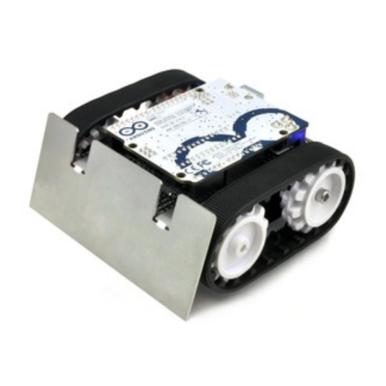
Zumo Shield for Arduino. Shield, Arduino Uno, and Zumo blade. A Zumo chassis, Zumo Shield, and Arduino can be combined to become a low-profile, Arduino-controlled tracked robot that is less than 10 cm on each side (small enough to qualify for Mini-Sumo competitions). -
Page 3: Contacting Pololu
Zumo blade) • 1/16″ black acrylic spacer plate (two pieces) Zumo Robot Kit for Arduino In addition to the shield and its included hardware, the Zumo robot kit for Arduino also includes these components: 1. Overview Page 3 of 28... - Page 4 The shield and chassis kit include extra parts like jumper wires, screws, nuts, and washers, so do not be concerned if you have some leftover hardware after assembling your Zumo. 1. Overview Page 4 of 28...
-
Page 5: Assembly
• 3 mm Allen wrench (hex key) • long-nose pliers (for bending the Zumo blade mounting tabs) 2.b. Assembling the Zumo Shield and chassis Please follow these instructions carefully to assemble your Zumo Shield and chassis properly. 2. Assembly Page 5 of 28... - Page 6 Pololu Zumo Shield for Arduino User's Guide © 2001–2012 Pololu Corporation Through-hole parts 1. Solder the included through- hole components to the shield: ◦ power switch ◦ reset pushbutton ◦ user pushbutton ◦ buzzer ◦ charging connector (1×2-pin female header) 2.
- Page 7 Pololu Zumo Shield for Arduino User's Guide © 2001–2012 Pololu Corporation 4. On the bottom of the board, trim the four Arduino header pins closest to the front of the board on each side to prevent them from contacting the motor housings. If you think there is a chance these pins might still touch the motor cases, you can put some electrical tape on the motors to act as insulation.
- Page 8 Pololu Zumo Shield for Arduino User's Guide © 2001–2012 Pololu Corporation Instead of making a wire connection, you can solder a 1×3 male header to the buzzer jumper holes to allow the use of a shorting block for connecting the buzzer. You can also use male headers and shorting blocks for the battery level jumper and compass jumpers if you have an Arduino Leonardo or an Arduino Uno with an SMD (surface mount) microcontroller.
- Page 9 Pololu Zumo Shield for Arduino User's Guide © 2001–2012 Pololu Corporation reasonably quick/efficient with this soldering; if the first attempt does not go well, remove the soldering iron and let the motor cool for a few seconds before trying again.
- Page 10 12. Cover the chassis and motors with the spacer plate pieces and then the Zumo shield. The holes in the spacer plate should line up with the through-holes in the shield resting on top of it. There is only one correct orientation for these plates.
- Page 11 Pololu Zumo Shield for Arduino User's Guide © 2001–2012 Pololu Corporation If you are also adding a basic sumo blade, you can either mount it now or add it later after you are done soldering the motors and battery contacts. To install the blade, first bend its mounting tabs to the appropriate angle.
- Page 12 Pololu Zumo Shield for Arduino User's Guide © 2001–2012 Pololu Corporation Battery contacts 15. Turn the chassis over and install the battery terminal contacts as shown in the picture below. Note that the two individual contacts should be inserted into the chassis so that their solder tabs protrude through the holes in the top of the chassis.
- Page 13 Pololu Zumo Shield for Arduino User's Guide © 2001–2012 Pololu Corporation 16. Solder the two individual contacts to the shield from the top. You might want to temporarily tape the contacts inside the chassis to hold them in place while you solder them, or you can use a battery to temporarily hold them in place while you solder.
- Page 14 20. At this point, you can add the silicone tracks by stretching them around the sprockets on each side of the chassis. Your Zumo Shield and chassis are now complete; just add batteries and an Arduino to get your Zumo robot moving! 2.
- Page 15 © 2001–2012 Pololu Corporation Disassembly If you later decide you want to solder additional parts to the Zumo Shield, it is possible to remove it from the chassis with some careful effort. 1. Remove the tracks from the chassis and carefully pull the drive sprockets off the motors.
-
Page 16: The Zumo Shield In Detail
A direct connection to the battery terminals is provided by the battery charger connector on the rear edge of the shield, which can be used to recharge the Zumo’s batteries without removing them from the chassis. The positive pin of the charge connector, on the left, is indicated by a plus sign (+). A charger like the... - Page 17 Buzzer The Zumo Shield comes with a buzzer that can be used to generate simple sounds and music (for example, you could use it to produce an audible countdown at the beginning of a sumo match). The buzzer control line is labeled 3.
-
Page 18: Front Expansion
Front expansion area A number of I/O, power, and ground connections are brought to the front of the Zumo Shield to allow the mounting of additional sensors and other components. The pinout of this front expansion area is detailed in Section 3.b. -
Page 19: Jumper Settings
If you use an Arduino Uno R2 or an older Arduino, which lack separate I²C pins, the SDA and SCL pins on the Zumo Shield will not be connected to anything. To use an I²C device on those pins, you can connect SDA to A4 and SCL to A5 yourself by bridging across those two sets of pins in the front expansion area. -
Page 20: 3-Axis Compass Module (Accelerometer And Magnetometer)
Please note that the SCL and SDA pins do not exist on Arduino hardware versions prior to the Uno R3, so you will have to manually connect SCL to analog pin 5 and SDA to analog pin 4 on the Zumo Shield in order to use the compass with an older Arduino. - Page 21 Arduino. The LSM303, level shifters, and I²C pull-up resistors are connected to the SCL and SDA pins on the Zumo Shield by default, but they can be disconnected by cutting traces to allow those pins to be used for other purposes.
-
Page 22: Schematic Diagrams
Pololu Zumo Shield for Arduino User's Guide © 2001–2012 Pololu Corporation 4. Schematic diagrams Schematic diagrams of the Zumo Shield are available as a downloadable PDF: Zumo Shield schematic diagrams (121k pdf). [http://www.pololu.com/file/download/zumo_shield_schematic.pdf?file_id=0J591] 4. Schematic diagrams Page 22 of 28... -
Page 23: Arduino Pin Assignment Table
Pololu Zumo Shield for Arduino User's Guide © 2001–2012 Pololu Corporation 5. Arduino pin assignment table Digital Zumo Shield function Notes/alternate functions pins digital I/O RX for programming and serial communication on Uno and older Arduinos digital I/O TX for programming and serial communication on Uno and older Arduinos digital I/O (front expansion) I²C SDA on Leonardo... -
Page 24: Zumo Shield Arduino Libraries
© 2001–2012 Pololu Corporation 6. Zumo Shield Arduino Libraries Our Zumo Shield Libraries make it easy to get started writing Arduino sketches to control your Zumo. A link to download the library and installation instructions can be found on the libraries’... -
Page 25: Example Project: Border-Detecting Sumo Robot
For border detection, it is sufficient to mount two reflectance sensors to the front of the Zumo, one on each side. This can easily be done by soldering two 1×3-pin female headers under the left and right corners of... -
Page 26: Arduino Sketch
7.b. Arduino sketch With the addition of QTR sensors, your Zumo should be able to drive around and stay within a sumo ring. The following example sketch demonstrates how to program an Arduino-controlled Zumo to do this. - Page 27 Pololu Zumo Shield for Arduino User's Guide © 2001–2012 Pololu Corporation // set according to the type of QTR sensor you're using #define QTR_THRESHOLD QTR_RC_THRESHOLD // these might need to be tuned for different motor types #define REVERSE_SPEED 200 // 0 is stopped, 400 is full speed...
- Page 28 9 and 10, might need to be changed to suit your environment. Upload the sketch to an Arduino mounted on a Zumo, place the Zumo on a sumo ring (or a similar large dark surface with a light border), and press the user pushbutton. Be ready to catch the Zumo in case it drives off the ring! If everything works right, the Zumo should sound a countdown with its buzzer and then start driving forward until it detects the ring border;...
Need help?
Do you have a question about the Zumo and is the answer not in the manual?
Questions and answers