
Subscribe to Our Youtube Channel
Related Manuals for Pololu 3pi+ 32U4


Summary of Contents for Pololu 3pi+ 32U4
- Page 1 Pololu 3pi+ 32U4 User’s Guide © 2001–2022 Pololu Corporation Pololu 3pi+ 32U4 User’s Guide https://www.pololu.com/docs/0J83/all Page 1 of 86...
-
Page 2: Table Of Contents
3. Assembling the 3pi+ 32U4 kit ........ -
Page 3: Overview
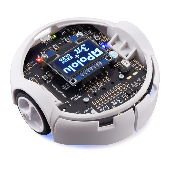
Pololu 3pi+ 32U4 User’s Guide © 2001–2022 Pololu Corporation 1. Overview The 3pi+ 32U4 is a versatile, high-performance, user-programmable robot that measures just 9.7 cm (3.8″) in diameter. At its heart is an ATmega32U4 AVR microcontroller from Microchip (formerly Atmel), and like our A-Star 32U4 programmable controllers [https://www.pololu.com/category/149/a-... - Page 4 Pololu 3pi+ 32U4 User’s Guide © 2001–2022 Pololu Corporation 1. Overview Page 4 of 86...
- Page 5 356] [https://www.pololu.com/ instead. The information in this user’s guide generally applies to both versions, and product/3760] the name “3pi+ 32U4” covers both the original (LCD) and OLED versions except where specific differences are noted. Pololu3piPlus32U4 Arduino library generally allows code [https://www.pololu.com/docs/0J83/7]...
-
Page 6: Configurations And Included Components
3pi will not work on the 3pi+ 32U4 without modification. 1.1. Configurations and included components The 3pi+ 32U4 OLED robot is available as a kit or fully assembled with three different motor options: 1. Overview Page 6 of 86... - Page 7 [https://www.pololu.com/product/4974] of your choice to [https://www.pololu.com/category/141/micro-metal-gearmotors-with-extended-motor-shafts] make a custom kit. The original (LCD) version of the 3pi+ 32U4 robot is also available in these three editions—Standard (assembled ), Turtle [https://www.pololu.com/product/3737] [https://www.pololu.com/product/3740] (assembled ), and Hyper [https://www.pololu.com/product/3738]...
- Page 8 Pololu 3pi+ 32U4 User’s Guide © 2001–2022 Pololu Corporation The kit versions of the 3pi+ 32U4 OLED robot include the following items: • 3pi+ Chassis Kit , which includes: [https://www.pololu.com/product/3725] ◦ 3pi+ chassis, with integrated 4×AAA battery holder and ball caster ◦...
- Page 9 Pololu 3pi+ 32U4 User’s Guide © 2001–2022 Pololu Corporation low-profile male header for the LCD instead) [https://www.pololu.com/product/2663] ◦ two magnetic encoder discs (12 CPR) [https://www.pololu.com/product/2599] ◦ four 3/16″ #2-56 screws nuts [https://www.pololu.com/product/2701] [https://www.pololu.com/product/1067] ◦ two 1/4″ #2-56 standoffs (OLED version only) [https://www.pololu.com/product/1940]...
- Page 10 Pololu 3pi+ 32U4 User’s Guide © 2001–2022 Pololu Corporation 1. Overview Page 10 of 86...
- Page 11 Pololu 3pi+ 32U4 User’s Guide © 2001–2022 Pololu Corporation 1. Overview Page 11 of 86...
- Page 12 © 2001–2022 Pololu Corporation The diagrams above show the contents of the 3pi+ 32U4 OLED kits. For the contents of the original 3pi+ 32U4 kits, which include an LCD and differ in a few other parts, refer to these diagrams instead.
-
Page 13: What You Will Need
• small 2 mm slotted screwdriver for adjusting the LCD contrast (original LCD version only) Kit assembly tools These additional items are needed or helpful for assembling the 3pi+ 32U4 robot kit: • soldering iron and solder (we recommend one with adjustable temperature control) •... -
Page 14: Supported Operating Systems
[https://www.pololu.com/product/2588] 1.3. Supported operating systems The 3pi+ 32U4 can be programmed using current versions of Microsoft Windows 11, Windows 10, Linux, and macOS. See our A-Star 32U4 bootloader page on GitHub [https://github.com/pololu/a-star/... -
Page 15: Contacting Pololu
Pololu 3pi+ 32U4 User’s Guide © 2001–2022 Pololu Corporation 2. Contacting Pololu We would be delighted to hear from you about any of your projects and about your experience with the 3pi+ 32U4. You can contact us directly or post on our forum [https://www.pololu.com/contact]... -
Page 16: Assembling The 3Pi+ 32U4 Kit
Pololu 3pi+ 32U4 User’s Guide © 2001–2022 Pololu Corporation 3. Assembling the 3pi+ 32U4 kit This section explains how to assemble the kit version of the 3pi+ 32U4 robot. If you have the pre- assembled version, you can skip to Section Section 1.1... - Page 17 3. Insert the four single battery contacts into the top of the chassis as shown. Adjust them until they are centered, straight, and match the height of the double battery contacts. 3. Assembling the 3pi+ 32U4 kit Page 17 of 86...
- Page 18 A good way to do this is to set the wheel on a flat surface (like a table top) and press the motor shaft into the wheel until it contacts the surface. 3. Assembling the 3pi+ 32U4 kit Page 18 of 86...
- Page 19 (see below). You might find it helpful to make a small bend at the tip of each lead to hook into the hole in the motor lead tab to hold it in place for soldering. 3. Assembling the 3pi+ 32U4 kit Page 19 of 86...
- Page 20 One easy way to accomplish this is to press the motor onto the disc while the disc is sitting on a flat surface, pushing until the shaft makes contact with that surface. 3. Assembling the 3pi+ 32U4 kit Page 20 of 86...
- Page 21 8. Place the motors into the channel in the middle of the chassis, aligning each gearbox with the grooves in the channel. The outer plate of the gearbox should be even with the edge of the chassis. 3. Assembling the 3pi+ 32U4 kit Page 21 of 86...
- Page 22 Pololu 3pi+ 32U4 User’s Guide © 2001–2022 Pololu Corporation Control board and bumper skirt 9. Solder the buzzer to the 3pi+ 32U4 control board. 3. Assembling the 3pi+ 32U4 kit Page 22 of 86...
- Page 23 10. Optional: This is a convenient time to add any other optional electronics or headers. 11. Place the control board on the chassis. The motor leads and single battery contacts should be inserted into the corresponding through holes. 3. Assembling the 3pi+ 32U4 kit Page 23 of 86...
- Page 24 It is usually easier to place the nut into the recess first and hold it there with a finger or piece of tape while inserting the screw or standoff. 3. Assembling the 3pi+ 32U4 kit Page 24 of 86...
- Page 25 Pololu 3pi+ 32U4 User’s Guide © 2001–2022 Pololu Corporation 13. Trim off the excess length of wire from each motor lead. 3. Assembling the 3pi+ 32U4 kit Page 25 of 86...
- Page 26 Pololu 3pi+ 32U4 User’s Guide © 2001–2022 Pololu Corporation 14. Solder the motor leads to the main board. 15. Double-check the alignment of the battery contacts, then solder the single battery contacts to 3. Assembling the 3pi+ 32U4 kit Page 26 of 86...
- Page 27 16. Optional: We recommend cutting the supports for the flaps on the front of the bumper skirt, since the flaps need to be able to deflect for the bump sensors on the 3pi+ 32U4 to work. The easiest way to do this is with a pair of flush cutters, but you can also use diagonal cutters or a knife (which might leave behind bumps that you need to clean up with a file).
- Page 28 Pololu 3pi+ 32U4 User’s Guide © 2001–2022 Pololu Corporation 17. Install the bumper skirt by pushing the clips on each side over the motor housings until they snap into place. 3. Assembling the 3pi+ 32U4 kit Page 28 of 86...
- Page 29 (screen) side of the display. Tip: Solder a single pin first and ensure the header is flush before making any additional solder joints. If the header 3. Assembling the 3pi+ 32U4 kit Page 29 of 86...
- Page 30 180° from its intended position. Incorrect positioning can damage the display or the control board, so please take care during this step to ensure that the display is plugged in properly. 3. Assembling the 3pi+ 32U4 kit Page 30 of 86...
- Page 31 Pololu 3pi+ 32U4 User’s Guide © 2001–2022 Pololu Corporation Mounting the 3pi+ 32U4 OLED display. Mounting the 3pi+ 32U4 LCD. Ball caster and battery covers 20. Press the ball caster into its socket on the bottom of the chassis. 3. Assembling the 3pi+ 32U4 kit...
- Page 32 Be careful not to reverse any of the batteries, or else the 3pi+ 32U4 will not operate properly (although the control board will not be damaged).
- Page 33 Pololu 3pi+ 32U4 User’s Guide © 2001–2022 Pololu Corporation 22. Secure the battery compartment covers by first hooking their tabs into the corresponding slots at the outer edges of the battery compartments… 3. Assembling the 3pi+ 32U4 kit Page 33 of 86...
- Page 34 Pololu 3pi+ 32U4 User’s Guide © 2001–2022 Pololu Corporation 23. …and then pivoting the covers down until the clips snap into place. 3. Assembling the 3pi+ 32U4 kit Page 34 of 86...
- Page 35 Pololu 3pi+ 32U4 User’s Guide © 2001–2022 Pololu Corporation The assembly of your 3pi+ 32U4 robot is now complete, and it is ready to be used! 3. Assembling the 3pi+ 32U4 kit Page 35 of 86...
- Page 36 Pololu 3pi+ 32U4 User’s Guide © 2001–2022 Pololu Corporation 3. Assembling the 3pi+ 32U4 kit Page 36 of 86...
-
Page 37: Using The Preloaded Demo Program
B button, which will take you to the main menu. On the original (LCD) version of the 3pi+ 32U4, if you hear a beep but do not see anything on the LCD, you might need to adjust the contrast potentiometer on the control board near the top right corner of the LCD. - Page 38 Pololu 3pi+ 32U4 User’s Guide © 2001–2022 Pololu Corporation away from bright incandescent or halogen lights, all of the sensors should return entirely black readings with the IR emitters off. 3. BumpSens: This demo lets you try out the bump sensors along the front side of the robot.
- Page 39 Pololu 3pi+ 32U4 User’s Guide © 2001–2022 Pololu Corporation 10. OLED or LCD: This demo shows you various text characters you can display on the OLED or LCD screen. Use the buttons to scroll through the pages of characters. 11. Music: Plays an adaptation of J. S. Bach’s Fugue in D Minor for microcontroller and buzzer, while scrolling a text display.
-
Page 40: The 3Pi+ 32U4 In Detail
Pololu 3pi+ 32U4 User’s Guide © 2001–2022 Pololu Corporation 5. The 3pi+ 32U4 in detail 5. The 3pi+ 32U4 in detail Page 40 of 86... -
Page 41: Microcontroller
The control board’s ATmega32U4 comes preloaded with the Arduino-compatible A-Star 32U4 USB bootloader , which allows it to be easily programmed using the [https://www.pololu.com/docs/0J83/9] Arduino IDE. For more information about programming the 3pi+ 32U4, see Section 5. The 3pi+ 32U4 in detail Page 41 of 86... -
Page 42: User Interface
5.2. User interface LEDs The 3pi+ 32U4 control board has seven indicator LEDs, three of which are user-controllable: • A yellow user LED is connected to Arduino digital pin 13, or PC7. You can drive this pin high in a user program to turn this LED on. - Page 43 Pushbuttons The 3pi+ 32U4 control board has five pushbuttons: a power button on the left, a reset button on the right, and three user pushbuttons located along the rear. The user pushbuttons, labeled A, B, and C, are on Arduino pin 14 (PB3), pin 30 (PD5), and pin 17 (PB0), respectively. Pressing one of these buttons pulls the associated I/O pin to ground through a resistor.
-
Page 44: Motors
Pololu 3pi+ 32U4 User’s Guide © 2001–2022 Pololu Corporation Display header The 3pi+ 32U4 OLED control board has a 1×7 header where you can connect a graphical OLED module with a low-profile male header. The included display has a [https://www.pololu.com/product/3760] resolution of 128×64 pixels and uses an... - Page 45 © 2001–2022 Pololu Corporation ratio combinations [https://www.pololu.com/category/141/micro-metal-gearmotors-with-extended-motor-shafts] to make your own custom 3pi+ 32U4 robot. Please keep in mind that using faster or lower-torque motors will make your robot more difficult to control. Two on-board motor drivers power the 3pi+ 32U4’s two Micro Metal Gearmotors.
-
Page 46: Quadrature Encoders
This behavior occurs more often with batteries that are drained than with freshly charged batteries, which means you might notice the performance of a 3pi+ 32U4 decreasing as its batteries start to run out. (For example, it might accelerate more slowly or even be unable to reach as high of a top speed.) It can also come into play with older or lower-quality batteries, which tend to have higher internal resistances that cause more significant voltage drops. - Page 47 Edition, channel B leads channel A when the motor is rotating in the forward direction; that is, B rises before A rises and B falls before A falls. (The waveforms in the diagram above would be produced by forward rotation.) 5. The 3pi+ 32U4 in detail Page 47 of 86...
-
Page 48: Line And Bump Sensors
Section 5.5. Line and bump sensors The 3pi+ 32U4 features five downward-facing line sensors and two forward-facing bump sensors. The five line sensors are on the underside of the board along the front edge and can help the 3pi+ distinguish between light and dark surfaces. Each reflectance sensor consists of a down-facing infrared (IR) emitter LED paired with a phototransistor that can detect reflected infrared light from the LED. - Page 49 These connections are made through traces connecting pairs of through-holes in the front expansion header of the 3pi+ 32U4 control board. A connection can be remapped by cutting the corresponding trace on the underside of the board and making a new connection between the sensor signal and another AVR pin of your choice.
-
Page 50: Inertial Sensors
Bottom view of the 3pi+ 32U4 Control Board, showing cuttable traces for remapping sensors. 5.6. Inertial sensors The 3pi+ 32U4 includes on-board inertial sensors that allow it to determine its own orientation by implementing an inertial measurement unit (IMU). The first chip, an ST... -
Page 51: Power
[https://github.com/pololu/minimu-9-ahrs-arduino] Notes on the magnetometer Please note that the magnetometer on the 3pi+ 32U4 can be affected by magnetic fields from the 3pi+ itself. These include magnets in the motors and encoders, electrical currents through the board, and hard iron distortions from metal (probably mostly from the batteries). The magnetometer is positioned as far away from the motors as possible to avoid interference from them, but hard iron distortions can still influence the readings significantly, making it difficult to accurately determine the 3pi+’s absolute... - Page 52 Pololu 3pi+ 32U4 User’s Guide © 2001–2022 Pololu Corporation Power switch circuit The 3pi+ 32U4 control board uses the patented latching circuit from the Pololu pushbutton power switch , which provides a solid-state power switch for your robot [https://www.pololu.com/product/2808] controlled with the on-board pushbutton. By default, this pushbutton can be used to toggle power: one push turns on power and another turns it off.
- Page 53 ATmega32U4 to reset.) 5 V and 3.3 V regulators VSW also supplies power to a 5 V regulator, whose output is designated R5V. This output is not 5. The 3pi+ 32U4 in detail Page 53 of 86...
- Page 54 (5V). Under typical conditions, roughly 0.7 A of current is available from the 5 V regulator. The 3pi+ 32U4 control board also contains a 3.3 V LDO that draws its power from the output of the logic power selection circuit. The output of the 3.3 V regulator is designated 3V3 and is used to supply the on-board inertial sensors and level shifters.
-
Page 55: Expansion Headers
5.8. Expansion headers The 3pi+ 32U4 control board has several expansion headers (primarily in two areas toward the front of the board) that break out many of the general-purpose I/O lines from the ATmega32U4 microcontroller. - Page 56 Pololu 3pi+ 32U4 User’s Guide © 2001–2022 Pololu Corporation 3pi+ 32U4 OLED Control Board pinout and peripherals. 5. The 3pi+ 32U4 in detail Page 56 of 86...
-
Page 57: Pin Assignments
The table below lists the most important pin assignments for the ATmega32U4 on the 3pi+ 32U4. This table is helpful if you want to add your own electronics to the 3pi+ 32U4, write your own low-level code for interfacing with the hardware, or just want to understand better how the 3pi+ 32U4 works. Each row represents a physical pin on the ATmega32U4. - Page 58 Pololu 3pi+ 32U4 User’s Guide © 2001–2022 Pololu Corporation it is an output. The “Note/alternate functions” column documents other features of the pin, although some of those features might be impractical to use. 5. The 3pi+ 32U4 in detail Page 58 of 86...
- Page 59 LCD version: LCD data line DB5 Timer4 PWM output A (OC4A) Yellow LED 13, LED_BUILTIN Timer3 input capture pin (ICP3) LCD version: LCD data line DB6 Divided system clock output 5. The 3pi+ 32U4 in detail Page 59 of 86...
- Page 60 Right encoder XORed input input (AIN0) External interrupt source (INT6) A5, 23 Right encoder input Analog input (ADC0) 3, SCL I²C clock for inertial sensors Timer0 PWM output B (OC0B) 5. The 3pi+ 32U4 in detail Page 60 of 86...
-
Page 61: Adding Electronics
AREF Analog reference 5.10. Adding electronics This section gives tips for how the 3pi+ 32U4 can be expanded with additional electronics. Freeing up I/O pins If you want your additional electronics to send or receive information from the AVR, you will need to connect them to one or more of the AVR’s I/O pins. - Page 62 On the original (LCD) version of the 3pi+ 32U4, if you have removed the LCD and do not need to use button A, this frees up pin 14 (PB3). Pin 14 is capable of digital input and output. Removing the LCD also frees up the LCD contrast potentiometer for other purposes.
-
Page 63: Avr Timers
[https://www.pololu.com/file/0J1790/3pi- (584k pdf) (original LCD version) plus-32u4-control-board-schematic.pdf] Dimensions Basic dimension diagrams are available as PDFs for the 3pi+ 32U4 Control Board by itself as well as the assembled 3pi+ 32U4 robot: • 3pi+ 32U4 OLED Control Board dimension diagram [https://www.pololu.com/file/0J1825/3pi- 5. - Page 64 3pi+ 32U4 Robot front, top, and side views [https://www.pololu.com/file/0J1797/3pi- (471k zip) (original LCD version) plus-32u4-robot-dxf.zip] 3D models of the 3pi+ 32U4 Control Board and robot are also available in STEP format: • 3pi+ 32U4 OLED Control Board 3D model [https://www.pololu.com/file/0J1826/3pi-plus-32u4-oled- (30MB step) control-board.step]...
-
Page 65: Programming The 3Pi+ 32U4
Service Pack 3, so we recommend Service Pack 3 over the hotfix. Before you connect your Pololu A-Star 32U4 (or another of our 32U4 family of boards) to a computer running Microsoft Windows, you should install its drivers: 1. - Page 66 Pololu 3pi+ 32U4 User’s Guide © 2001–2022 Pololu Corporation 4. Windows will not tell you when the installation is complete, but it should be done after a few seconds. Windows 10, Windows 8, Windows 7, and Windows Vista users: After installing the drivers, your computer should automatically recognize the device when you connect it via USB.
-
Page 67: Programming Using The Arduino Ide
After installing the drivers and plugging in an A-Star, in the “Ports (COM & LPT)” category of the Device Manager, you should see a COM port for the A-Star’s running sketch named “Pololu A-Star 32U4”. You might see that the COM port is named “USB Serial Device” in the Device Manager instead of having a descriptive name. - Page 68 URL on a new line. Adding a Boards Manager index for Pololu boards in the Arduino IDE’s Preferences dialog. 4. Click the “OK” button to close the Preferences dialog.
- Page 69 8. After the installation finishes, click the “Close” button to close the Boards Manager dialog. 9. In the Tools > Board menu, select the “Pololu A-Star 32U4” entry. If you do not see your device listed in the Board menu, try restarting the Arduino IDE.
- Page 70 Pololu 3pi+ 32U4 User’s Guide © 2001–2022 Pololu Corporation Windows 10 Device Manager showing the A-Star’s virtual COM port. 11. Open up the “Blink” Arduino example, which can be found under File > Examples > 01.Basics > Blink. The code in this example will blink the yellow LED. When you select the Blink example, a new Arduino IDE window will open up.
- Page 71 Pololu 3pi+ 32U4 User’s Guide © 2001–2022 Pololu Corporation USB port, then Windows might take several seconds to recognize the A-Star bootloader. The bootloader times out after 8 seconds and goes back to running the sketch, so the upload might fail if Windows does not recognize it quickly enough. If this happens, try again. If you...
-
Page 72: Programming Using Avr-Gcc And Avrdude
Pololu 3pi+ 32U4 User’s Guide © 2001–2022 Pololu Corporation the LED. The A-Star 32U4 boards are similar enough to the Arduino Leonardo that you do not actually have to install the add-on. If you want to, you can just select the “Arduino Leonardo”... - Page 73 Pololu 3pi+ 32U4 User’s Guide © 2001–2022 Pololu Corporation that can be used to upload programs to the A-Star bootloader. If the version of GNU Make avrdude/] that comes with WinAVR crashes on your computer, we recommend using the Pololu version of GNU Make [https://github.com/pololu/make/releases]...
- Page 74 Pololu 3pi+ 32U4 User’s Guide © 2001–2022 Pololu Corporation MCU=atmega32u4 CFLAGS=-g -Wall -mcall-prologues -mmcu=$(MCU) -Os LDFLAGS=-Wl,-gc-sections -Wl,-relax CC=avr-gcc TARGET=main OBJECT_FILES=main.o all: $(TARGET).hex clean: rm -f *.o *.hex *.obj *.hex %.hex: %.obj avr-objcopy -R .eeprom -O ihex $< $@ %.obj: $(OBJECT_FILES) $(CC) $(CFLAGS) $(OBJECT_FILES) $(LDFLAGS) -o $@ program: $(TARGET).hex...
-
Page 75: Pololu3Piplus32U4 Arduino Library
© 2001–2022 Pololu Corporation 7. Pololu3piPlus32U4 Arduino library The 3pi+ 32U4 can be programmed from the Arduino IDE as described in the preceding sections. To help interface with all the on-board hardware on the control board, we provide the Pololu3piPlus32U4 library. The Pololu3piPlus32U4 library documentation [https://pololu.github.io/... -
Page 76: The 3Pi+ 32U4 Usb Interface
On a Windows computer, you can see the virtual serial port by going to your computer’s Device Manager and expanding the “Ports (COM & LPT)” list. You should see a COM port labeled “Pololu A- Star 32U4”. In parentheses after the name, you will see the name of the port (e.g. “COM3” or “COM4”). - Page 77 Br@y Terminal PuTTY [https://www.pololu.com/docs/0J23] [https://sites.google.com/site/terminalbpp/] TeraTerm Kermit [https://www.chiark.greenend.org.uk/~sgtatham/putty/] [http://ttssh2.osdn.jp/] , and GNU Screen . Many [http://www.columbia.edu/kermit/ck80.html] [http://www.gnu.org/software/screen/] computer programming environments also support sending and receiving bytes from a serial port. 8. The 3pi+ 32U4 USB interface Page 77 of 86...
-
Page 78: The A-Star 32U4 Bootloader
Pololu 3pi+ 32U4 User’s Guide © 2001–2022 Pololu Corporation 9. The A-Star 32U4 Bootloader Our 32U4 family of boards come with a USB bootloader that can be used in conjunction with the Arduino IDE or AVRDUDE to load new programs onto the device. This section documents some technical details of the bootloader for advanced users who want to better understand how it works. - Page 79 Pololu 3pi+ 32U4 User’s Guide © 2001–2022 Pololu Corporation The startup logic for the A-Star 32U4 bootloader. Brown-out detection Unlike many other ATmega32U4 boards, our 32U4 family of boards have brown-out detection enabled. The brown-out threshold is 4.3 V, and if the voltage on VCC goes below this then the AVR will reset.
- Page 80 Pololu 3pi+ 32U4 User’s Guide © 2001–2022 Pololu Corporation The bootloader was designed so that the user program can detect brown-out resets. To do so, check to see if the BORF bit in the MCUSR register is set, and then clear it later. Here is some example code...
-
Page 81: Reviving An Unresponsive 3Pi+ 32U4
Pololu 3pi+ 32U4 User’s Guide © 2001–2022 Pololu Corporation 10. Reviving an unresponsive 3pi+ 32U4 In order to load a new program onto your A-Star 32U4 device, you will need to get it into bootloader mode and send programming commands to it over its virtual serial port using appropriate software. If... - Page 82 1. Connect the device to your computer via USB. 2. In the “Tools” menu, open the “Board” sub-menu and check to see if the “Pololu A-Star 32U4 (bootloader port)” entry is visible. If this entry is visible, you can skip to step 6.
- Page 83 Blink example that can be found under File > Examples > 01.Basics > Blink. After reviving your device, be sure to change the Board setting back to “Pololu A-Star 32U4” and select the right Port.
-
Page 84: Reviving Using Avrdude
By following the instructions above, the malfunctioning program on the device will be erased and the device will stay in bootloader mode indefinitely. You can now load another program onto it using the Arduino IDE or AVRDUDE. 10. Reviving an unresponsive 3pi+ 32U4 Page 84 of 86... -
Page 85: Related Resources
[https://www.microchip.com/en-us/tools-resources/ develop/microchip-studio] • AVRDUDE [http://www.nongnu.org/avrdude/] • AVR Freaks [https://www.avrfreaks.net/] Datasheets for some of the components found on the 3pi+ 32U4 control board are available below: • ATmega32U4 documentation [https://www.microchip.com/en-us/product/ATmega32u4] • Texas Instruments DRV8838 motor driver datasheet [https://www.pololu.com/file/0J806/ (1k redirect) drv8838.pdf.redirect] •... - Page 86 Pololu 3pi+ 32U4 User’s Guide © 2001–2022 Pololu Corporation • ST LIS3MDL 3-axis magnetometer datasheet [https://www.pololu.com/file/0J1089/LIS3MDL.pdf] (2MB pdf) • Texas Instruments TPS2113A power multiplexer datasheet [https://www.pololu.com/file/ (1k redirect) 0J771/tps2113a.pdf.redirect] Finally, we would like to hear your comments and questions on the Pololu Robotics Forum [https://forum.pololu.com/]...
Need help?
Do you have a question about the 3pi+ 32U4 and is the answer not in the manual?
Questions and answers