Advertisement
Quick Links
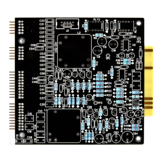
EQ573-II Assembly guide
Safety warning
The kits are main powered and use potentially lethal voltages. Under no circumstance should someone undertake the
realisation of a kit unless he has full knowledge about safely handling main powered devices.
Please read the "DIY guide" before beginning.
Print or open the following documents :
• EQ573-II Schematics
• EQ573-II Components layout
• EQ573-II Parts list
Follow this guide from item number 1 till the end, in this order. The assembly order is based on components height, from
low to high profile, in order to ease the soldering process : The component you are soldering is always taller than the
previously assembled ones and it is pressing nicely against the work area foam.
Soldering
All the PCB holes are metallized. It means the connection between the top and bottom pads is already
done. The parts must be soldered only from below (unless differently stated).
Use only small diameter solder, 0.5 or 0.7 mm, 1mm maximum. Use the minimum possible amount of
solder. Bad joints are almost always caused by too much solder.
Cut the component leads and pins totally flush with the PCB after soldering. A too long tail could create
an electric connection with the side plate.
Here are two excellent introduction to soldering videos:
http://www.eevblog.com/2011/06/19/eevblog-180-soldering-tutorial-part-1-tools/
http://www.eevblog.com/2011/07/02/eevblog-183-soldering-tutorial-part-2/
EQ573-II Assembly guide – Main board
1.
PCB split
Split the PCB into 4 parts along the grooves.
Use extra thin sandpaper to polish all the rough
sides.
Copyright ©2020 to today SoundSkulptor
Document revision 1.1 – Last modification : 27/05/21
www.soundskulptor.com
Advertisement

Related Manuals for Sound Skulptor EQ573-II


Summary of Contents for Sound Skulptor EQ573-II
- Page 1 Here are two excellent introduction to soldering videos: http://www.eevblog.com/2011/06/19/eevblog-180-soldering-tutorial-part-1-tools/ http://www.eevblog.com/2011/07/02/eevblog-183-soldering-tutorial-part-2/ EQ573-II Assembly guide – Main board PCB split Split the PCB into 4 parts along the grooves. Use extra thin sandpaper to polish all the rough sides.
- Page 2 Document revision 1.1 – Last modification : 27/05/21 EQ573-II Assembly guide – Main board PCB to PCB connector J3a, J4a, J5a, J6a Insert the male 2x10 and 2x5 connectors into the corresponding female parts and position them on the main PCB back. The female connectors must sit flat on the side.
-
Page 3: Ceramic Capacitors
Document revision 1.1 – Last modification : 27/05/21 EQ573-II Assembly guide – Main board Ceramic capacitors Add the ceramic capacitors. IC Socket Insert and solder the two 8 pins socket. Warning : Make sure to respect the socket direction, marked by a notch. - Page 4 Document revision 1.1 – Last modification : 27/05/21 EQ573-II Assembly guide – Main board Test pins Solder the 7 test pins TP1, TP2, TP3, TP4, 0V, V+, V-. 10. Tantalum capacitors Add C61, C69. The plus lead is the longest.
-
Page 5: Electrolytic Capacitors
Document revision 1.1 – Last modification : 27/05/21 EQ573-II Assembly guide – Main board 13. Electrolytic capacitors Add all the other electrolytic capacitors of the main PCB. Warning : The +lead must go into the +hole. Do not reverse (they may explode !) 14. - Page 6 Document revision 1.1 – Last modification : 27/05/21 EQ573-II Assembly guide – Main board 17. Visual check At this point, brush the solder side with a hard tooth brush to remove any remaining solder bits. Make a full visual check. Any missing component on the board ? Any remaining component in the box ? When everything looks correct, proceed with the other boards assembly.
- Page 7 Document revision 1.1 – Last modification : 27/05/21 EQ573-II Assembly guide – Switches board 22. 12 positions Rotary switch Add the 12 positions rotary switch SW6. Warning : The position of the switches is critical for a good front-plate matching and a smooth potentiometer rotation.
- Page 8 www.soundskulptor.com Document revision 1.1 – Last modification : 27/05/21 EQ573 Assembly guide – Potentiometers board 27. Resistor Add the resistor R17 horizontally (green identifier in the parts list). 28. Potentiometers Add P1 and P3 (10KA). Insert the potentiometers into the PCB holes from the solder side, making sure the pins fit into the corresponding PCB pads.
- Page 9 www.soundskulptor.com Document revision 1.1 – Last modification : 27/05/21 EQ573 Assembly guide – Final assembly 32. Front panel assembly Insert and attach the front panel with three M2.5x8mm black screws. 33. Chassis plate assembly Attach the chassis plate to the front plate with two M3x6mm black screws. 34.
- Page 10 www.soundskulptor.com Document revision 1.1 – Last modification : 27/05/21 EQ573 Assembly guide – Final assembly EQ573 Assembly guide – Link cable assembly (for connecting to MP573) 39. Cable striping Split the 2 sections of the wire on a length of 2.5cm. Strip 1.5cm of each section.
- Page 11 www.soundskulptor.com Document revision 1.1 – Last modification : 27/05/21 EQ573 Assembly guide – Link cable assembly (for connecting to MP573) 40. Connectors soldering If you own a crimping tool, crimp a contact on each wire. If not, tin the wire tips and solder a contact to each wire. 41.
Need help?
Do you have a question about the EQ573-II and is the answer not in the manual?
Questions and answers