Advertisement
Quick Links
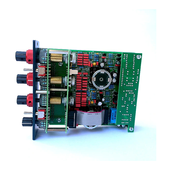
EQ573 Assembly guide
Safety warning
The kits are main powered and use potentially lethal voltages. Under no circumstance should someone undertake the
realisation of a kit unless he has full knowledge about safely handling main powered devices.
Please read the "DIY guide" before beginning.
Print or open the following documents :
• EQ573 Schematics
• EQ573 Components layout
• EQ573 Parts list
• EQ573 Setup guide
Follow this guide from item number 1 till the end, in this order. The assembly order is based on components height, from
low to high profile, in order to ease the soldering process : The component you are soldering is always taller than the
previously assembled ones and it is pressing nicely against the work area foam.
EQ573 Assembly guide – Main board
1.
Diodes
Add D1 to D5. Use a lead forming tool to bend the leads at 0.4".
Warning
: Make sure to respect the direction of the diodes which is marked by a ring on the component
and a double line on the PCB marking.
2.
Resistors
Add R17 to R66.
Control the resistor values with a digital multimeter. Bend the leads at 0.4" with a lead forming tool.
3.
Test pins
Solder the 5 test pins TP1 to TP5.
4.
Ceramic capacitors
Add C79, C87.
5.
Film capacitors
Add C24 to C49, C51, C53 to C55, C57 to C75, C80, C81, C84, C88, C89, C92.
Copyright ©2011 to today SoundSkulptor
Document revision 1.1 – Last modification : 01/05/14
www.soundskulptor.com
Advertisement

Related Manuals for Sound Skulptor EQ573


Summary of Contents for Sound Skulptor EQ573
- Page 1 : The component you are soldering is always taller than the previously assembled ones and it is pressing nicely against the work area foam. EQ573 Assembly guide – Main board Diodes Add D1 to D5.
- Page 2 Document revision 1.1 – Last modification : 01/05/14 EQ573 Assembly guide – Main board Tantalum capacitors Add C78, C86. The plus lead is always on the right when facing the marking with the leads pointing down. Warning : The +lead must go into the +hole. Do not reverse ! Connector Solder the 2 x 8 pins header CN3A.
-
Page 3: Electrolytic Capacitors
Document revision 1.1 – Last modification : 01/05/14 EQ573 Assembly guide – Main board 10. Relays Add RLY1 and RLY2. 11. Electrolytic capacitors Add C19 to C23, C76, C77, C82, C83, C85, C90, C91, C93 to C96. Solder one lead first, adjust verticality then solder the second lead. -
Page 4: Rotary Switches
Document revision 1.1 – Last modification : 01/05/14 EQ573 Assembly guide – Main board 13. Visual check At this point, brush the solder side with a hard tooth brush to remove any remaining solder bits. Make a full visual check. Any missing component on the board ? Any remaining component in the box ? When everything looks correct, proceed with the other boards assembly. - Page 5 Document revision 1.1 – Last modification : 01/05/14 EQ573 Assembly guide – Switches board 19. Pin header This part requires some care and you will need a good soldering iron with a thin tip. Insert the 2x40 pins header, straight pins forward from the solder side, as shown on the diagram.
- Page 6 Document revision 1.1 – Last modification : 01/05/14 EQ573 Assembly guide – IO board 23. Resistors Add R1 to R16. Control the resistor values with a digital multimeter. Bend the leads at 0.4” with a lead forming tool. 24. Ceramic capacitors Add C1, C2, C7, C8, C10.
- Page 7 Document revision 1.1 – Last modification : 01/05/14 EQ573 Assembly guide – Final assembly 30. Side panel Attach the side panel to the front plate with two M3x6 black countersunk screws. 31. Main PCB Install the main PCB on the side panel, inserting the 2x40 pins header into the PCB holes. Attach it with two M3x6 screws and two shake-proof washers in the front and two M3x20 male/female spacers in the back.
- Page 8 Document revision 1.1 – Last modification : 01/05/14 EQ573 Assembly guide – Final assembly 36. Potentiometers PCB assembly Attach the potentiometers PCB to the switches PCB with three M3x6 screws. Do not tighten yet. Attach the front panel again with three M3x6 black countersunk screws.
- Page 9 Document revision 1.1 – Last modification : 01/05/14 EQ573 Assembly guide – Final assembly EQ573 Assembly guide – Link cable assembly (for connecting to MP573) Connector soldering Insert the 3 pins female connector into the second row of holes (circled red).
- Page 10 Document revision 1.1 – Last modification : 01/05/14 EQ573 Assembly guide – Link cable assembly (for connecting to MP573) Cable soldering Insert the cable 3 wires from beneath the PCB into the 3 unplated holes, red in centre, yellow on the “Y” side. Insert the red and yellow wire tips into the corresponding PCB holes and solder.
Need help?
Do you have a question about the EQ573 and is the answer not in the manual?
Questions and answers