Table of Contents
Advertisement
Quick Links
Eport-E20/Eport-E20-PIN Super Port User Manual
Overview of Characteristic
MIPS MCU with
2MB Flash
Use
FreeRTOS
Operation System
Support
TCP/IP/Telnet/Modbus
Support
Serial To 10/100M Ethernet
Support 10/100M Ethernet
Support Easy Configuration Through a
Support Security Protocol Such As
Support Web OTA
Single +3.3V Power Supply
Size: 50 x 23 x 11 mm (L x W x H)
FCC/CE/RoHS Certificated
http://www.iotworkshop.com
Eport-E20/Eport-E20-PIN
Super Port User Manual
and
128KB RAM
TCP Protocol
Conversion, Serial Speed Upto 921600 bps
Auto-Negotiation
TLS/AES/DES3
Wirelss Upgrade
V 1.2
Web
Interface
- 1 -
Advertisement
Table of Contents

Related Manuals for HF Eport-E20


Summary of Contents for HF Eport-E20
- Page 1 Eport-E20/Eport-E20-PIN Super Port User Manual Eport-E20/Eport-E20-PIN Super Port User Manual V 1.2 Overview of Characteristic MIPS MCU with 2MB Flash 128KB RAM FreeRTOS Operation System Support TCP/IP/Telnet/Modbus TCP Protocol Support Serial To 10/100M Ethernet Conversion, Serial Speed Upto 921600 bps ...
-
Page 2: Table Of Contents
Eport-E20/Eport-E20-PIN Super Port User Manual TABLE OF CONTENTS TABLE OF CONTENTS TABLE OF CONTENTS TABLE OF CONTENTS ................2 LIST OF FIGURES ..........................3 LIST OF TABLES ..........................4 HISTORY ............................4 PRODUCT OVERVIEW ......................5 1.1. General Description ......................5 1.2. -
Page 3: List Of Figures
Eport-E20-PIN Pins Map........................9 Figure 5. Eport-E20 Mechanical Dimension ....................11 Figure 6. Eport-E20 Mechanical Dimension ....................12 Figure 7. Eport-E20-PIN recommended PCB layout ..................12 Figure 8. Eport-E20 Product Number Defination ..................13 Figure 9. Eport-E20 EVK ..........................13 Figure 10. -
Page 4: List Of Tables
Eport-E20 Super Port User Manual LIST OF TABLES Table1. Eport-E20 Series Module Technical Specifications ................5 Table2. Eport-E20 Pins Definition ........................8 Table3. Eport-E20-PIN Pins Definition ........................ 9 Table4. Absolute Maximum Ratings: ......................... 10 Table5. Power Supply & Power Consumption: ....................10 Table6. -
Page 5: Product Overview
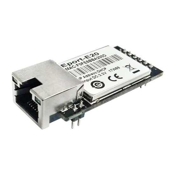
Time-To-Market with very low risk. The Eport-E20 series integrates all serial to Ethernet functionality into a low-profile, 50 x 23 x 11mm standard RJ45 module package that can be easily mounted on main PCB with application specific circuits and even not change your original Design. -
Page 6: Key Application
-45 ~ 105° C, 5 ~ 95% RH(no condensation) Input Voltage 3.3V Working Current ~100mA Power <400mW 1.3. Key Application The Eport-E20 device connects serial device to Ethernet networks using the TCP/IP protocol: ⚫ Remote equipment monitoring ⚫ Asset tracking and telemetry ⚫ Security Application ⚫... -
Page 7: Hardware Introduction
Eport-E20 Super Port User Manual 2. HARDWARE INTRODUCTION The Eport-E20 series is a complete solution for serial port device connecting to network. Packageed into a RJ45 connector, this powerful device supports a 10/100BASE-T Ethernet connection, a reliable and proven operating system stored in flash memory, an embedded web server, a full TCP/IP protocol stack,and standards-based (AES) encryption. -
Page 8: Eport-E20 Pins Definition
Eport-E20 Super Port User Manual 2.2. Eport-E20 Pins Definition Figure 3. Eport-E20 Pins Map Table2. Eport-E20 Pins Definition DES3cribtion Net Name Signal Type Comments GPIO GPIO1 Can be configured to UART1:TXD2 GPIO GPIO2 Can be configured to UART1:RXD2 UART0 Can be configured to GPIO “Low”... -
Page 9: Eport-E20-Pin Pins Definition
Eport-E20 Super Port User Manual When there are data transmiting and receiving, This LED will flashing. If there is no data transmit and receive, It will output High. LED1_Link Pin When Ethernet connected normal, It will output Low, If there is no Ethernet connection, It will output High. -
Page 10: Electrical Characteristics
Eport-E20 Super Port User Manual 2.4. Electrical Characteristics Table4. Absolute Maximum Ratings: Parameter Condition Min. Typ. Max. Unit Storage Temperature Range ° C Maximum Soldering Temperature IPC/JEDEC J-STD-020 ° C Supply Voltage Voltage on any I/O pin ESD (Human Body Model HBM) TAMB=25°... -
Page 11: Ethernet Led Interface
Yellow 10/100Mbps Green Have Data 2.7. Eport-E20 Mechanical Size The dimensions of Eport-E20 are defined as following picture (mm): Figure 5. Eport-E20 Mechanical Dimension 2.8. Eport-E20-PIN Mechanical Size The dimensions of Eport-E20-PIN are defined as following picture (mm): Shanghai High-Flying Electronics Technology Co., Ltd... -
Page 12: Figure 6. Eport-E20 Mechanical Dimension
Eport-E20 Super Port User Manual Figure 6. Eport-E20 Mechanical Dimension Figure 7. Eport-E20-PIN recommended PCB layout Shanghai High-Flying Electronics Technology Co., Ltd - 12 -... -
Page 13: Order Information
Eport-E20 Product Number Defination 2.10. Evaluation Kits We provide evaluation kit for user to learn to use Eport-E20(Eport-E20-PIN is the same as Eport-E20, so for evaluation, juse use Eport-E20). Evaluation kit picture is as following, User can use RS232, USB Serial or Ethernet interface to configure parameters, manage equipment and do some function test. -
Page 14: Typical Application
Press down the button more than 3s and then loose Reload to restore factory setting 2.11. Typical Application Figure 10. Eport-E20 Hardware Typical Application Notes: nRST- Input.Hardware reset signal. Effective Low. There is internal pull-up resistor to 3.3V and no external pull-up resistor needed. MCU put nRST signal to low for at least 10ms if need to reset the device. -
Page 15: Software Function
Eport-E20 Super Port User Manual TXD/RXD- UART port data transmit and receive signal. 2.12. Software Function Refer to “IOT_Device_Series_Software_Funtion” for detailed usage. Shanghai High-Flying Electronics Technology Co., Ltd - 15 -... -
Page 16: Appendix A: Hw Reference Design
APPENDIX A: HW REFERENCE DESIGN Figure 11. HW REFERENCE DESIGN Detailed Eport-E20 Evluation Board Design source files, pls access IOTworkshop or High-Flying web download page or contact with High-Flying technical support people to acquire. Shanghai High-Flying Electronics Technology Co., Ltd... -
Page 17: Appendix B:references
Eport-E20 Super Port User Manual APPENDIX B:REFERENCES B.1.More materials http://www.hi-flying.com/ethernet-iot/super-ethernet/eport-e20 Shanghai High-Flying Electronics Technology Co., Ltd - 17 -... -
Page 18: Appendix C: Contact Information
Eport-E20 Super Port User Manual APPENDIX C: CONTACT INFORMATION ------------------------------------------------------------------------------------------------------------ Address: Room 1002,Building 1,No.3000,Longdong Avenue,Pudong New Area,Shanghai,China,201203 Web: www.iotworkshop.com www.hi-flying.com Contact: Sales: sales@iotworkshop.com Support: support@iotworkshop.com Service: service@iotworkshop.com Business: business@iotworkshop.com ---------------------------------------------------------------------------- ------------------------------- For more information about IOTworkshop modules, applications, and solutions, please visit our web site www.iotworkshop.com...
Need help?
Do you have a question about the Eport-E20 and is the answer not in the manual?
Questions and answers