Table of Contents
Advertisement
Quick Links
Features
Piping :
Protection class transmitter:
Protection class transducer:
Display:
Keypad:
Displayed data: istantaneous flowrate, flow totalizer
Housing:
Mounting:
Output::
Total accuracy:
Repeatibility:
Linearity:
Basic measurement period:
Serial port:
Programmable frequency output:
Relay output:
Medium speed:
Working temperature:
Instrument humidity: non condensing 85% RH (40°C)
Sensor process temperature:
Sensor humidity:
non condensing 98% RH (40°C)
Power supply:
Dimensions:
Weight:
General
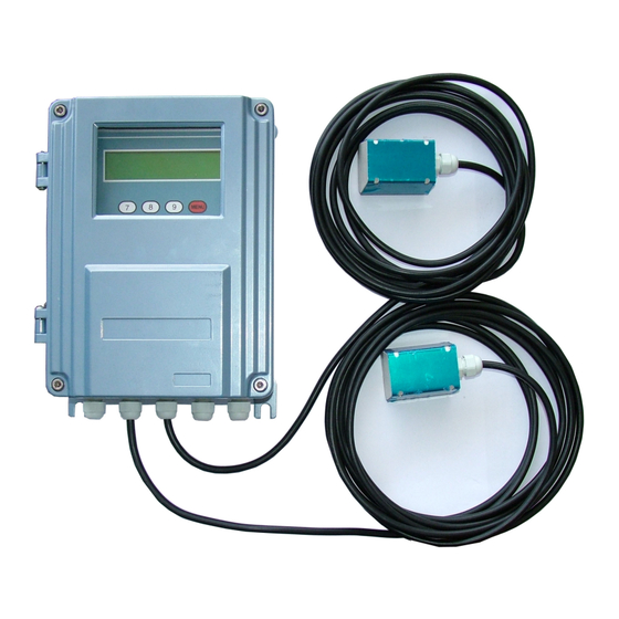
The SGM-100F is composed by a digital converter and two clamp-on or insertion type ultrasonic transducers.
It is designed to measure the fluid velocity of a liquid inside a closed conduit. The transducers are a non-
contacting, clamp-on type, which provide benefits of non-fouling operation and easy installation.
The DSP digital technology (Digital Signal Processing) ensure a low sensibility of the instrument against
potential transient factors.
SGM-100F
Transit time ultrasonic flowmeter
20mm-4000mm
IP65
IP68
2x20 digit alphanumeric
backlighted
4x4
Aluminium
wall
Sel. 4÷20m A or 0÷20mA
± 1%
±0,2÷0,5%
±0,5%
500ms
RS 232 (optional RS 485)
12÷9999HZ
for pulse totalizer or alarm
±32m/s
-30÷80°C
0÷150°C
230Vac / 24Vdc
251x192x80mm
3,1Kg
applied solutions for the application
825B109E
Advertisement
Table of Contents

Related Manuals for SGM LEKTRA SGM-100F


Summary of Contents for SGM LEKTRA SGM-100F
- Page 1 3,1Kg General The SGM-100F is composed by a digital converter and two clamp-on or insertion type ultrasonic transducers. It is designed to measure the fluid velocity of a liquid inside a closed conduit. The transducers are a non- contacting, clamp-on type, which provide benefits of non-fouling operation and easy installation.
-
Page 2: Working Principle
The SGM-100F operates by alternately transmitting and receiving a frequency modulated burst of sound energy between the two transducers and measuring the transit time that takes the sound to travel between them. The difference in measured transit time is directly and exactly related to the velocity of the liquid inside the pipe (fig.1). - Page 3 SGM-100F - Features Features Mechanical dimensions Applications 1. water, sewage with low particle content and seawater 2. water supply and drainage water 3. power plants, nuclear power plant, thermal and hydropower plants, heat energy, boiler feed water and energy management system 4.
-
Page 4: Features/Operation
SGM-100F - Features/Operation Product Identification Every instrument has an 8 digit identification number (ESN) which provides the information of version and manufacring date. It is displayed on menu M61 and can be employed for instrumentation management. Specifications a t l... - Page 5 - Operation Power on Standard power supply of SGM-100F is 230VAC. Please check power supply voltage before connecting the unit. Once the instrument is switched on, it will run a self diagnostic program. If there’s any anomaly the corresponding error message will be displayed. Generally, there should be no display of error messages, and the flow meter will go...
- Page 6 ESN information and alarms for totalizer data display M90÷M94 for diagnostic M97÷M99 command windows (contact SGM LEKTRA) M+0÷M+8 additional fucntions, as calculator, and for displaying total working hours, turn-on and turn-off times and date and time of the single operations. Parameters setting...
-
Page 7: Installation
3.2. Transducers installation The SGM-100F transducers are made of piezoelectric crystals, both for transmitting and receiving the ultrasonic signals through the wall of the liquid piping system. The measurement is realized by measuring the traveling time difference of the ultrasonic signals. Since the difference is very small, the spacing and the alignment of the transducers are important factors for the accuracy of the measurement and the performance of the measuring system. - Page 8 SGM-100F - Installation How to proceed with the installation: (1) Locate an optimum position on the pipe, which has to be in good condition (no rust) (2) Clean and dust the pipe surface. (3) Apply adeguate coupler on the spot where the transducers have to be installed and leave no gap between the pipe surface and the transducers.
- Page 9 SGM-100F - Installation 3.2.3 Z method installation It is commonly used when the pipe diameter is between 300 and 500 millimeters. 3.2.4 W method installation It is usually used on little pipes with a diameter from 10 to 100 millimiters.
- Page 10 SGM-100F - Installation 3.2.6 Insert sensor installation Steps for a correct installation: 1- If the pipe is placed inside the wall, check that there’s sufficient space for the mounting of the insertion sensor (min. distance between the wall and the pipe = 540mm) 2- Procure a drilling tool 3- Enter pipe parameter (in menu M23 choose option 5.
- Page 11 SGM-100F - Installation 6- Drill the pipe 1 sensor 2 bottom of ball valve 3 ball valve 4 screw 5 tight screw 6 connection 7 cable 7- Insert the sensor 1 sensor 2 bottom of ball valve 3 ball valve...
- Page 12 SGM-100F - Installation Installation check-up Through the checkup of the installation, one can: check the receiving signal strength, the signal quality Q value, the traveling time difference of the signals, the estimated liquid speed, the measured traveling time of the signals and the calculated traveling time ratio.
- Page 13 SGM-100F - Use How to check if the instrument works properly When ‘R’ is displayed in the lowest right corner of LCD display, the instrument is working properly. If an ‘H’ flashes on that place, there could be poor signal received. Please refer to the chapters on diagnosis.
- Page 14 SGM-100F - Use 4.12 How to get a range factor for calibration A range factor is the ratio between the ‘actual flow rate’ and the indicated value by the flow meter. The range factor can be determined by calibration with flow calibration equipment.
- Page 15 SGM-100F - Use no receiving signal poor signal received flow meter not in normal measurement mode reverse flow overflow of the Frequency Output flow out of the setted range There are two out-of-normal-range alarms in this instrument. They are called #1 Alarm and #2 Alarm. The flow range can be user-configurable through M73, M74, M75, M76.
-
Page 16: Menu Structure
SGM-100F - Menu structure Menu structure Menu window details WARNING!!!! On the menu window from M00 to M09 the display will not show the menu number on the top left corner! Display flow rate, net totalizers Display flow rate, flow velocity... - Page 17 SGM-100F - Menu structure Window for selecting fluid type for standard liquids that the user need not know the liquid speed include: (0) Water; (1) Sea Water; (2) Kerosene; (3) Gasoline; (4) Fuel oil; (5) Crude Oil; (6) Propane at -45C;...
- Page 18 Calendar. Press to mofify and use to skip the digit that need no adjusting Display Version information and Electronic Serial Number (ESN) that are unique for each SGM-100F series flow meter. The users can employ the ESN for instrumentation management...
- Page 19 SGM-100F - Menu structure Output AL4 Correspond value range Input the frequency range for the frequency output. The highest range is 0Hz-9999Hz. Default value is 1-1001 Hz Enter a flow rate value that corresponds to lower frequency Enter a flow rate value that corresponds to higher frequency LCD display backlight control.
- Page 20 SGM-100F - Menu structure Displays signal strenght, signal quality and time ratio on the upper right corner Displays the Time Ratio between the measured total transit time and the calculated time. If the pipe parameters are entered correctly and the transducers are installed properly, the value should be in the range of 100÷3 %.
-
Page 21: Troubleshooting
The SGM-100F has a self-diagnosis system which detects hardware problems. The instrument will show “*F” in the top left corner of the display and it will be necessary to power on again the SGM-100F in order to see the error... -
Page 22: Communication Protocol
The remaining volatge is in the range of 3.70 and 3,90V. SGM-100F - Communication Protocol Communication Protocol 7. 1 General The SGM-100F has a standard communication interface and a complete set of communication protocol. 7.2 Interface pin-out definition for battery recharge, positive input not used OCT output... - Page 23 SGM-100F - Communication Protocol Command Function Data Format DQD(CR) Return flow rate per day ±d.ddddddE±dd(CR) LF * DQH(CR) Return flow rate per hour ±d.ddddddE±dd(CR) LF DQM(CR) Return flow rate per minute ±d.ddddddE±dd(CR) LF DQS(CR) Return flow rate per second ±d.ddddddE±dd(CR) LF...
-
Page 24: Warranty
SGM-100F - Warranty Products supplied by SGM LEKTRA are guaranteed for a period of 12 (twelve) months from delivery date according to the conditions specified in our sale conditions document. SGM LEKTRA can choose to repair or replace the Product. If the Product is repaired it will mantain the original term of guarantee, whereas if the Product is replaced it will have 12 (twelve) months of guarantee.
Need help?
Do you have a question about the SGM-100F and is the answer not in the manual?
Questions and answers