Table of Contents
Advertisement
Quick Links
Features
• Pipe dimension range:
• Measure range:
• Fluid conductivity:
• Sensor material:
• Lining materials:
PTFE from DN10 to DN500;
rubber from DN40 to DN1000
• Housing materia:
• Electrodes materials:
• Remote version operating temperature:
• Compact version operating temperature:
• Accuracy:
• Repeatability:
• Analog outpu:
4÷20mA; max. load 750
• Communication protocol:
• Digital output:
• Pulse output:
• Alimentazione:
• Consumption:
• Protection compact version:
gland M16x1,5 for elect. connection
• Protection remote version:
• Display:
forward and reverse flow rate
direct, reverse and net total
General
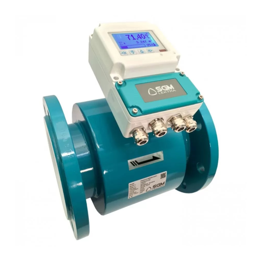
A complete magnetic flowmeter system consists of two components: the Smag62 microprocessor-based integral-mount
magneti flowmeter transmitter and a flowtube.The flowtube is installed in-line with process piping, either vertically
or horizontally. Coils located on opposite sides of the flowtube create a magnetic field, and conductive liquid moving
through the magnetic field generates a voltage that is detected by two electrodes.The transmitter controls the generation
of the magnetic field and senses the voltage detected by the electrodes. Based on the sensed voltage, the transmitter
calculates a flow rate and produces analog and frequency output signals proportional to this flow rate.
Pmag
Electromagnetic flowmeter
DN10 ÷ DN1000
<0,2m
/h ÷ >30000m
/h
3
3
>5 S/cm
SS321
epoxy printing aluminum
SS316; Hastelloy C
<80°C
-20÷75°C
±0,5%
±0,1%
Modbus (opt.)
0÷5000Hz
24Vdc pull-up
85÷265Vac or 24Vdc
<6W
IP67 with 4 cable
IP67/IP68 only pipe
(opt.)
backlit LCD
Compact digital system, for conductive liquids (>5 S/cm),
even with a limitated content of suspended solids.
Measurement range: from <0,2m
Typical measurement accuracy: ±0.5%
Power supply 85÷265Vac or 24Vdc
Pmag GB
/h to >30000m
/h
3
3
Advertisement
Table of Contents

Related Manuals for SGM LEKTRA Pmag


Summary of Contents for SGM LEKTRA Pmag
- Page 1 Pmag Pmag GB Electromagnetic flowmeter Features • Pipe dimension range: DN10 ÷ DN1000 • Measure range: <0,2m /h ÷ >30000m • Fluid conductivity: >5 S/cm • Sensor material: SS321 • Lining materials: PTFE from DN10 to DN500;...
-
Page 2: Technical Data
Pmag62 - Features 1. Features 1.1 Flow Rate Range Capable of processing signals from fluids that are traveling between to 10 m/s for both forward and reverse flow in all flowtube sizes.. 1.2 Fluid Conductivity Fluid must have conductivity of at least 5 microsiemen/cm. 1.3 Power Supply 85 ÷... -
Page 3: Flow Tables
Pmag - Features 3. FLOW TABLES Page 3 of 24... -
Page 4: Compact Version
Pmag - Features 4. DIMENSION 4.1 Compact version n i l Page 4 of 24... -
Page 5: Remote Version
Pmag - Features 4.2 Remote version n i l Page 5 of 24... -
Page 6: Safety Measure
Never place anything through the flowtube for the purpose of lifting or gaining leverage.Liner damage can render the flowtube useless. 5.3.1 Identify Options and Configurations Standard application of the Pmag includes control of the flowtube coils and one or more following configurations or options: - 4÷20 mA Output... -
Page 7: Environmental Considerations
5.7 Environment of the installation 1) The Pmag must by mounted in dry and well ventilated site. Not install the instrument in the place where the water is easily accumulated. 2) The instrument should not be exposed. Shelter is needed where the instrument is installed outside. -
Page 8: Preparation For Operation
Pmag - Installation 5.9 Grounding The grounding of the instrument must be satisfied because the signal the instrument measured is very weak, only a few milli-voltages, even at its full range. See figure 9 for the grounding position. There are two requirements for grounding: 1) The sensor and the fluid must be equipotential. -
Page 9: Electric Connection
- Connect + DC. - Connect - DC. 6.3 OUTPUT Satisfy these requirements before attempting to install and operate the Pmag. 6.3.1 Analog output The loop may be powered from the transmitter itself. Resistance in the loop must be 750ohms or less. -
Page 10: Quick Start-Up
8. LOCAL OPERATOR INTERFACE (LOI) The LOI option is an operator communications center for the Pmag. Through the LOI, the operator can access any transmitter function for changing configuration parameter settings, checking totalized values, or other functions. 8.1 SAFETY MESSAGES Instructions and procedures in this section may require special precautions to ensure the safety of the personnel performing the operations. - Page 11 Pmag - Setting 8.4 LOI ROTATION Each magnetic flowmeter installation is different from application to application; therefore, the LOI display can be rotated to accommodate various setups using the following procedure: 1. Remove power from the transmitter Unscrew and remove the LOI cover. Do not remove the cover in explosive atmospheres when the circuit is alive.
-
Page 12: Display Page
Pmag - Setting 8.6 DISPLAY PAGE The Pmag has three pages to display data and status, press to change page If there is no alarm, this page will not appear 8.7 LOI MENU Press the key from run mode: the display will show the list of configuration menu as shown here next. - Page 13 Pmag - Setting 8.7.1 Basic Configuration (Basic) Press the key from run mode: the display will be as shown here next, then press to enter the "Basic" menu Press the keys to select the desired function and press the key to access 8.7.1.1 - PV Units...
- Page 14 Pmag - Setting Press the key from run mode: the display will be as shown here next. With select the decimal number places to display. Press to confirm, the display will be as shown here next. press the key to exit and confirm the selection; press the key to exit and delete the selection.
- Page 15 Pmag - Setting 8.7.2.2.1 - Qmax (m3/h) Set the flow measurement 100%. This value adjusts the analog output end scale (20mA) and the frequency output end scale. The range is related to the sensor DN. Press the key from run mode: the display will be as shown here next.
- Page 16 Pmag - Setting 8.7.2.2.5 - Direction This parameter enables the flow direction measurement Default: Fwd (forward) Range: Fwd (forward); Rev (reverse); Bid. (bidirectional) Press the key from run mode: the display will be as shown here next. With select the parameter setting.
- Page 17 Pmag - Setting Press to confirm, the display will be as shown here next. press the key to exit and confirm the selection; press the key to exit and delete the selection. 8.7.2.3.3 - Pulsewidth (ms) Sets the pulse width in ms.
- Page 18 Pmag - Setting Press the key from run mode: the display will be as shown here next. With select the parameter setting. Press to confirm, the display will be as shown here next. press the key to exit and confirm the selection; press the key to exit and delete the selection.
- Page 19 Pmag - Setting Press the key from run mode: the display will be as shown here next. With select the parameter setting. Press to confirm, the display will be as shown here next. press the key to exit and confirm the selection; press the key to exit and delete the selection.
- Page 20 Pmag - Setting 8.7.2.5.4 - REV Preset Predetermines the negative totalizer value Default: 0000000000 Range: 1÷9999999999 Press the key from run mode: the display will be as shown here next. With change the digit, with moves the cursor. Press to confirm, the display will be as shown here next.
- Page 21 Pmag - Setting Press the key from run mode: the display will be as shown here next. With select the parameter setting. Press to confirm, the display will be as shown here next. press the key to exit and confirm the selection; press the key to exit and delete the selection.
-
Page 22: Keyboard Lock
Pmag - Setting 8.7.3.4 - K Character Press the key to enter the function. “K Character "is the measure correction coefficient. Default: 1. Range: 0.97÷1.03 To access the menu "Total Set" may need to enter the correct password. The default password: 0003 After entering, you can change the password Note: If forget password can not access the menu. -
Page 23: Troubleshooting
Pmag - Troubleshooting 9. TROUBLESHOOTING Problems in the magnetic flowmeter system are usually indicated by incorrect output readings from the system, error messages, or failed tests. Consider all sources when identifying a problem in your system. Process Noise: In some circumstances, process conditions themselves can cause the meter output to be unstable. The basic procedure for addressing a noisy process situation is outlined below. - Page 24 - Factory test certificate In conformity to the company and ceck procedure I certify that the equipment: Pmag ........part nb........is conform to the technical requirements on Technical Data and it is made in conformity to the Company procedure Quality Control Manager .........
Need help?
Do you have a question about the Pmag and is the answer not in the manual?
Questions and answers