
Related Manuals for Laird AC4490


Summary of Contents for Laird AC4490
- Page 1 AC4490 User Guide Version 4.5 Americas: +1-800-492-2320 Europe: +44-1628-858-940 Hong Kong: +852-2923-0610 Embedded Wireless Solutions Support Center: http://ews-support.lairdtech.com www.lairdtech.com/ramp...
- Page 2 The preceding statement must be included as a CAUTION statement in manuals for OEM products to alert users on FCC RF Exposure compliance. Caution: Any change or modification not expressly approved by Laird could void the user’s authority to operate the equipment.
-
Page 3: Table Of Contents
AC4490 User Guide Version 4.5 ONTENTS AC4490 RF Transceiver ..........................4 Overview ..............................4 Features ................................ 4 Theory of Operation ............................ 5 RF Architecture............................5 Modes of Operation ........................... 5 AC4490 Configuration ..........................8 AT Commands ............................8 Command Descriptions ..........................10 API Control .............................. -
Page 4: Ac4490 Rf Transceiver
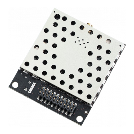
AC4490 RF T RANSCEIVER The compact AC4490 900 MHz transceiver can replace miles of cable in harsh industrial environments. Using field-proven frequency hopping spread spectrum (FHSS) technology which needs no additional FCC licensing in the Americas, OEMs can easily make existing systems wireless with little or no RF expertise. -
Page 5: Theory Of Operation
PERATION RF Architecture The AC4490 utilizes a server-client network architecture where all clients synchronize their hopping to the server. The server transmits a beacon during the first 20 milliseconds of every hop. The client transceivers listen for this beacon and, upon hearing it, assert their In_Range Low and synchronize hops with the server. - Page 6 Once in Command mode, the radio interprets all data received as command data. Command data can be either EEPROM configuration or on-the-fly commands. Figure 1: Pending RF Buffer Flow Laird Connectivity Solutions Support Center: Americas: +1-800-492-2320 Europe: +44-1628-858-940 http://ews-support.lairdtech.com...
- Page 7 AC4490 User Guide Version 4.5 Figure 2: Pending Data in Buffer Flow Laird Connectivity Solutions Support Center: Americas: +1-800-492-2320 Europe: +44-1628-858-940 http://ews-support.lairdtech.com Hong Kong: +852 2923 0610 www.lairdtech.com/ramp...
-
Page 8: Ac4490 Configuration
ONFIGURATION AT Commands The AT Command mode implemented in the AC4490 creates a virtual version of the Command/Data pin. The “Enter AT Command Mode” Command asserts this virtual pin Low (to signify Command Mode) and the “Exit AT Command Mode” Command asserts this virtual pin High (to signify Data). Once this pin has been asserted Low, all On-the-Fly CC Commands documented in the manual are supported. - Page 9 Address EEPROM Byte Write 0xCC 0xC1 Start Address Length Data Starting Address Length Data written Soft Reset 0xCC 0xFF Available only on AC4490LR-1000 transceivers. Laird Connectivity Solutions Support Center: Americas: +1-800-492-2320 Europe: +44-1628-858-940 http://ews-support.lairdtech.com Hong Kong: +852 2923 0610 www.lairdtech.com/ramp...
-
Page 10: Command Descriptions
The OEM Host issues this command to change the channel of the transceiver. Command: 0xCC 0x02 <Channel> Number of Bytes Returned: 2 Response: 0xCC <Channel> Parameter Range: <Channel> = RF Channel in use Laird Connectivity Solutions Support Center: Americas: +1-800-492-2320 Europe: +44-1628-858-940 http://ews-support.lairdtech.com Hong Kong: +852 2923 0610... - Page 11 Note: This command is valid only for client transceivers. Command: <0xCC> <0x06> Number of Bytes Returned: 2 Response: <0xCC> <Channel> Parameter Range: <Channel> = RF Channel currently being used Laird Connectivity Solutions Support Center: Americas: +1-800-492-2320 Europe: +44-1628-858-940 http://ews-support.lairdtech.com Hong Kong: +852 2923 0610...
- Page 12 Command: <0xCC> <0x11> Number of Bytes Returned: 4 Response: <0xCC> <MAC3> <MAC2> <MAC1> Parameter Range: <MAC> = 0x00 - 0xFF corresponding to 3 LSB’s of destination MAC Address Laird Connectivity Solutions Support Center: Americas: +1-800-492-2320 Europe: +44-1628-858-940 http://ews-support.lairdtech.com Hong Kong: +852 2923 0610...
- Page 13 5: Enable Auto Chan. Modification bit 4: Enable Auto Dest. Modification bit 3: Ignored bit 2: Ignored bit 1: Auto Channel bit 0: Auto Destination Laird Connectivity Solutions Support Center: Americas: +1-800-492-2320 Europe: +44-1628-858-940 http://ews-support.lairdtech.com Hong Kong: +852 2923 0610 www.lairdtech.com/ramp...
- Page 14 This value will default to 0xFF on a client and 0x00 on a server if no valid RSSI measurement has been made since power-up. Command: <0xCC> <0x22> Number of Bytes Returned: 2 Response: <0xCC> <Last Valid RSSI> Laird Connectivity Solutions Support Center: Americas: +1-800-492-2320 Europe: +44-1628-858-940 http://ews-support.lairdtech.com Hong Kong: +852 2923 0610...
- Page 15 3.3V or 1.65V. A broad filter has been implemented on the transceiver and there is no advantage to using a slower update period. Generally, a faster update period is preferred. Laird Connectivity Solutions Support Center: Americas: +1-800-492-2320 Europe: +44-1628-858-940 http://ews-support.lairdtech.com...
- Page 16 5.01 7.94 10.5 11.22 15.85 13.5 22.39 93.5 14.5 28.18 15.5 35.48 16.5 44.67 110.5 50.12 114.5 17.5 56.23 117.5 18.5 70.79 19.5 89.13 Laird Connectivity Solutions Support Center: Americas: +1-800-492-2320 Europe: +44-1628-858-940 http://ews-support.lairdtech.com Hong Kong: +852 2923 0610 www.lairdtech.com/ramp...
- Page 17 The OEM Host issues this command to determine when the RF transmit buffer is empty. The Host will not receive the transceiver response until that time. Command: <0xCC> <0x30> Number of Bytes Returned: 2 Response: <0xCC> <0x00> Laird Connectivity Solutions Support Center: Americas: +1-800-492-2320 Europe: +44-1628-858-940 http://ews-support.lairdtech.com Hong Kong: +852 2923 0610...
- Page 18 Note: 0xD8 is a twos complement representation of -40 – 0. Command: <0xCC> <0xA5> Number of Bytes Returned: 2 Response: <0xCC> <Temp> Parameter Range: <Temp> = Temperature at last calibration Laird Connectivity Solutions Support Center: Americas: +1-800-492-2320 Europe: +44-1628-858-940 http://ews-support.lairdtech.com Hong Kong: +852 2923 0610...
- Page 19 Multiple byte writes of up to 128 bytes are allowed. An EEPROM boundary exists between addresses 0x7F and 0x80. No single EEPROM write command shall write to addresses on both sides of that EEPROM boundary. See EEPROM Parameters. Laird Connectivity Solutions Support Center: Americas: +1-800-492-2320 Europe: +44-1628-858-940 http://ews-support.lairdtech.com Hong Kong: +852 2923 0610...
-
Page 20: Api Control
Response: None API Control API Control is a powerful feature offered by the AC4490. When enabled, the API Receive Packet, API Transmit Packet, API Send Data Complete and Enhanced API Receive Packet features provide dynamic packet routing and packet accounting ability to the OEM host, thereby eliminating the need for extensive programming on the OEM host side. - Page 21 (transparent to OEM host). If an acknowledgement is not received, the packet is retransmitted until one is received or all retries are used. Laird Connectivity Solutions Support Center: Americas: +1-800-492-2320 Europe: +44-1628-858-940 http://ews-support.lairdtech.com...
-
Page 22: Eeprom Parameters
Mode 0x02 0x02 = Client Baud Rate 0x42 0x00 - 0xFC Low byte of the interface baud rate. Default baud rate is 57600. 0xFF Laird Connectivity Solutions Support Center: Americas: +1-800-492-2320 Europe: +44-1628-858-940 http://ews-support.lairdtech.com Hong Kong: +852 2923 0610 www.lairdtech.com/ramp... - Page 23 0 = Use destination address 1 = Use auto destination bit-3: Client Auto Channel 0 = Disable Auto Channel 1 = Enable Auto Channel bit-2: RTS Enable Laird Connectivity Solutions Support Center: Americas: +1-800-492-2320 Europe: +44-1628-858-940 http://ews-support.lairdtech.com Hong Kong: +852 2923 0610 www.lairdtech.com/ramp...
- Page 24 0xFF System ID 0x76 0x00 - 0x01 Similar to network password. Radios must have the same system ID to communicate 0xFF with each other. Laird Connectivity Solutions Support Center: Americas: +1-800-492-2320 Europe: +44-1628-858-940 http://ews-support.lairdtech.com Hong Kong: +852 2923 0610 www.lairdtech.com/ramp...
- Page 25 0xE3, 0xFF oxE3 = Enable Auto Calibrate Calibrate 0xFF 0xFF = Disable Auto Calibrate DES Key 0xD0 0x00 - 56-bit Data Encryption key 0xFF Laird Connectivity Solutions Support Center: Americas: +1-800-492-2320 Europe: +44-1628-858-940 http://ews-support.lairdtech.com Hong Kong: +852 2923 0610 www.lairdtech.com/ramp...
- Page 26 Radio RF The Radio RF section manages the following settings: Designates AC4490 type. In each network, there must be only one server. All other Client / Server AC4490 units must be programmed as clients. The number of clients in the network is not limited;...
- Page 27 Server B will not be affected and can communicate with its clients. Appendix I: API for further details and sample configuration. Max Power provides a means for controlling the RF output power of the AC4490. Max Power Output power and current consumption can vary by as much as ±10% per transceiver for a particular Max Power setting.
- Page 28 A number from 0 to 256 that provides added security to each independent network System ID of AC4490 units. The System ID is used in conjunction with the Channel Number and serves as an RF password to maintain secure transfers of data. The combination of the Channel Number and System ID must be unique to each network of AC4490s to establish communication.
-
Page 29: Appendix I: Api
I: API PPENDIX The API feature set of the AC4490 provides powerful, dynamic packet routing capabilities to the OEM host. The number of API configurations is endless since individual radios can all be configured differently to suit the OEM host’s varying needs. Two of the most common implementations are described in the following pages. - Page 30 Depending on the API configuration of the SAP, the packet will be received in one of two formats: Receive API Time Division Multiple Access Network Laird Connectivity Solutions Support Center: Americas: +1-800-492-2320 Europe: +44-1628-858-940 http://ews-support.lairdtech.com Hong Kong: +852 2923 0610...
- Page 31 It is important not to have two loopback repeaters in range of each other as they will continuously transmit data back and forth. Laird Connectivity Solutions Support Center: Americas: +1-800-492-2320 Europe: +44-1628-858-940 http://ews-support.lairdtech.com...
- Page 32 Radio A transmits during time interval t = 1 Radio B transmits during time interval t = 2 Radio N transmits during time interval t = N – 1 Laird Connectivity Solutions Support Center: Americas: +1-800-492-2320 Europe: +44-1628-858-940 http://ews-support.lairdtech.com Hong Kong: +852 2923 0610 www.lairdtech.com/ramp...
- Page 33 This type of implementation requires careful planning and should allow enough time for retries if necessary. When full duplex is enabled, the radio which initiated the session (SAP) will transmit during the even numbered hops and the remote radios will transmit only during odd numbered hops. Laird Connectivity Solutions Support Center: Americas: +1-800-492-2320 Europe: +44-1628-858-940 http://ews-support.lairdtech.com...
-
Page 34: Appendix Ii: Sync-To-Channel
Note: For a period of one (1) year from the date of purchase, Laird warrants the transceiver against defects in materials and workmanship. Laird will not honor this warranty (and this warranty will be automatically void) if there has been any: (1) Tampering, signs of tampering, or opening the transceiver’s case. - Page 35 Hop Master server. All collocated servers must be programmed to the same channel set. There are 32 available channels for the CL4490-1000, as shown in Table Table 8: RF Channels for AC4490 RF Channel Frequency Details & Regulatory Countries...
-
Page 36: How Do I Configure Sync To Channel
You will be prompted to install the software on your PC. Once the install is completed, you can open the software from Start -> All Programs -> Laird Technologies Wireless -> Laird Technologies Config.exe. Note: Items 2-6 in the following list correlate to the numbered items in Figure 8. - Page 37 6. Go to the Configure tab and click the Read Radio button at the bottom right of the screen. A message stating “Read Successful” should appear after a successful read (Figure Laird Connectivity Solutions Support Center: Americas: +1-800-492-2320 Europe: +44-1628-858-940 http://ews-support.lairdtech.com...
- Page 38 A Write Successful prompt will appear after a successful write. Note that the values are shown using hexadecimal representation; this can be changed to decimal notation by double-clicking on the word “Hex” (it will change to “Dec”). Laird Connectivity Solutions Support Center: Americas: +1-800-492-2320 Europe: +44-1628-858-940 http://ews-support.lairdtech.com...
- Page 39 8. Configure all clients that will communicate with the Hop Master Server as clients in Auto Destination and with the same RF Channel Number as the Hop Master Server (Figure 11), and then press the Write Radio button. Laird Connectivity Solutions Support Center: Americas: +1-800-492-2320 Europe: +44-1628-858-940 http://ews-support.lairdtech.com Hong Kong: +852 2923 0610...
- Page 40 Radio RF section, set the Sync to Channel to the RF channel of the Hop Master (Figure 12). Press the Write Radio button to write the changes to the radios EEPROM. Laird Connectivity Solutions Support Center: Americas: +1-800-492-2320 Europe: +44-1628-858-940 http://ews-support.lairdtech.com...
- Page 41 10. Configure the clients that will communicate with Server #2 as Clients in Auto Destination and with the same RF Channel Number as Server #2 (Figure 13). Press the Write Radio to write the changes to the radios EEPROM. Laird Connectivity Solutions Support Center: Americas: +1-800-492-2320 Europe: +44-1628-858-940 http://ews-support.lairdtech.com Hong Kong: +852 2923 0610...
-
Page 42: I've Configured My Radios, What's Next
If a centralized network does not work and all servers are not in range of the hop master, a daisy chain network can be used as shown in Figure Laird Connectivity Solutions Support Center: Americas: +1-800-492-2320 Europe: +44-1628-858-940 http://ews-support.lairdtech.com... - Page 43 AC4490 User Guide Version 4.5 Figure 14: Sample Centralized Sync to Channel Network configuration Laird Connectivity Solutions Support Center: Americas: +1-800-492-2320 Europe: +44-1628-858-940 http://ews-support.lairdtech.com Hong Kong: +852 2923 0610 www.lairdtech.com/ramp...
- Page 44 AC4490 User Guide Version 4.5 Figure 15: Sample Daisy Chain Sync to Channel Network configuration Laird Connectivity Solutions Support Center: Americas: +1-800-492-2320 Europe: +44-1628-858-940 http://ews-support.lairdtech.com Hong Kong: +852 2923 0610 www.lairdtech.com/ramp...
-
Page 45: Related Documents And Files
AC4490 User Guide Version 4.5 ELATED OCUMENTS AND ILES The following additional AC4490 technical documents are available from the AC4490 product page (Documentation and Datasheet tabs) located on the Laird website: http://www.lairdtech.com/products/ac4490 Product Brief AC4490 Hardware Integration Guide ... - Page 46 Copyright © 2013 Laird Technologies, Inc. All rights reserved. The information contained in this manual and the accompanying software programs are copyrighted and all rights are reserved by Laird Technologies, Inc. Laird Technologies, Inc. reserves the right to make periodic modifications of this product without obligation to notify any person or entity of such revision.
Need help?
Do you have a question about the AC4490 and is the answer not in the manual?
Questions and answers