Table of Contents
Advertisement
Quick Links
Advertisement
Table of Contents

Related Manuals for VDO AcquaLink A2C59501997

Summary of Contents for VDO AcquaLink A2C59501997
- Page 1 AcquaLink - 7” TFT display Instruction manual v. 1.0...
-
Page 3: Table Of Contents
The instructions for installing and using Nav Box and Nav Control are available at www.vdo-marine.com, document codes: Nav Box: A2C12119500 Nav Control: A2C99832800 Customer service and warranty In the event of malfunction, fault or for information on the warranty, contact a VDO partner. To find a partner, visit www.vdo-partner.com. -
Page 4: Getting Started
Getting started Description AcquaLink 7" is a multifunctional display connected to the VDO CAN bus network of the AcquaLink system. The display lets you view data from the engines and the sensors connected to Nav Box through NMEA 2000, NMEA 0183, SAE J1939 or directly connected through analog inputs. Up to four engines can be monitored from the display. - Page 5 The VDO logo and software version followed by the AcquaLink logo appear when turned on. In addition, if before turned off the display was controlled by Nav Control or if on the VDO CAN bus network there is only one display, the Nav Control icon appears.
- Page 6 Function of the Nav Control buttons Button Function Hold down: Turn on/off Nav Control and all the devices connected to the VDO CAN bus network Briefly press: Change the display brightness level Hold down: Change the color of the background and of the characters...
- Page 7 4. Change/remove data pages selecting the best layout and data to be viewed (see "Data page configuration" on page 12). 5. Enable/disable the alarms on the VDO CAN bus, NMEA 2000 and SAE J1939 networks (see "Alarm management" on page 24). 7” TFT display | Instruction manual v. 1.0 | © 2018 Continental Automotive Switzerland AG...
-
Page 8: Data Pages
Data pages What are data pages Data pages display data received from the various sources. The pages are grouped into four favorites groups, which can contain up to eleven pages each. Groups configuration is free, and a page can be inserted into more than one group. - Page 9 Data pages Managed data Unit of measure Information Engine rpm Engine boost pressure bar, psi, kPa Engine coolant temp °C, °F Engine coolant pressure bar, psi, kPa Engine oil temp °C, °F Engine oil pressure bar, psi, kPa Engine exhaust temp °C, °F Engine hours Engine trim...
- Page 10 Data pages Unit of measure Information Depth below keel m, ft, fath Depth below waterline m, ft, fath Tilt (Roll/Pitch) ° Speed over ground (SOG) km/h, mph, kn Sumlog (STW) km/h, mph, kn Avg speed through water km/h, mph, kn Velocity made good km/h, mph, kn Distance through water...
- Page 11 Data pages Unit of measure Information Drift speed km/h, mph, kn X-track error (cross track error) km, mi, nm Distance to waypoint km, mi, nm Bearing to waypoint ° Velocity to waypoint km/h, mph, kn 7” TFT display | Instruction manual v. 1.0 | © 2018 Continental Automotive Switzerland AG...
-
Page 12: Data Page Configuration
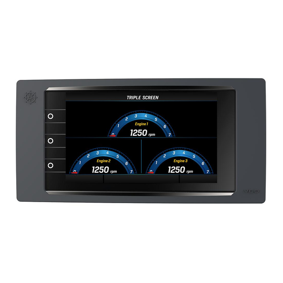
Data page configuration Configuration via layout Each display page can be customized using five editable layouts and three default layouts. Layout description Layout SINGLE: single box. The data value is Layout DUAL: two boxes, up to two data values. numeric or displayed by a gauge. The data values are numeric or displayed by a gauge. - Page 13 Data page configuration Layout TRIPLE: three boxes, up to three data Layout QUAD: four boxes, from up to four data values. The data values are numeric or displayed by values. The data values are numeric or displayed a gauge. by a gauge. Layout RADIO: MediaBox page.
- Page 14 Data page configuration Layout VIDEO: video input display. Layout MAST: four pages with data about: Apparent wind angle (AWA), Apparent wind speed (AWS),Speed through water (STW), True heading. 7” TFT display | Instruction manual v. 1.0 | © 2018 Continental Automotive Switzerland AG...
- Page 15 Data page configuration Viewable data in Nav Dash layout Gauges Viewable data Nav Dash 1 Engine revolutions Nav Dash 2 Depth below transducer Nav Dash 3 (large) Rudder angle Apparent wind angle (AWA) Apparent wind speed (AWS) True wind angle True wind speed True heading Speed through water (STW)
- Page 16 Data page configuration Edit a page (analog gauges layout) Following is an example of how to edit a page with a SINGLE by applying a three gauge NAV DASH layout: 1. Press to access the main menu and then scroll and select FAVORITES. 2.
- Page 17 Data page configuration Change the number of engines to be displayed 1. Press to access the main menu and then scroll and select USER CONFIG. 2. Scroll and select Engine amount, then select Amount of engines. 3. Scroll and select the new number of engines. 4.
-
Page 18: General Settings
General settings Menu layout USER CONFIG 7” TFT display | Instruction manual v. 1.0 | © 2018 Continental Automotive Switzerland AG... - Page 19 General settings Menu description USER CONFIG Note: the underlined value/command is the default value/command. Setting Description Possible values/commands Race timer > Set race timer From 00:00 to 99:59 hh:mm (00:10). Timer or chronometer. The time is If = 00:00 the chronometer function starts, counted backwards or forwards starting from the set value.
-
Page 20: System Settings
System settings Menu layout SYSTEM CONFIG Note*: the units of measure depend on parameter SYSTEM CONFIG > Units 7” TFT display | Instruction manual v. 1.0 | © 2018 Continental Automotive Switzerland AG... - Page 21 Restoration of factory default settings for groups groups of devices Reset > Reset tacho instances Restoration of engine IDs connected to tachometers on the VDO CAN bus network 7” TFT display | Instruction manual v. 1.0 | © 2018 Continental Automotive Switzerland AG...
- Page 22 System settings Setting Description Possible values/commands Reset > Restoration of all settings, including MediaBox, Reset factory to factory settings Reset > Available only with MediaBox connected. Only Reset MediaBox restore MediaBox settings to factory settings Unit of measure Managed units of measure are provided below: Datum Metric Imperial...
- Page 23 System settings Damping The function makes the displayed values more stable. It is available for wind and compass data. Example With medium-strong wind, to prevent the wind speed value from quickly and suddenly changing, set damping to High or Medium. On the contrary, with slight or no wind, set No or Low for a reactive indication.
-
Page 24: Alarm Management
Alarm management Signal mode The alarms are processed and transmitted by Nav Box to the display based on data read by the NMEA 2000, SAE J1939 and NMEA 0183 networks or the connected analog and digital sensors. The alarms concern the engines on the network and other navigation parameters. When an alarm is triggered, the pop-up with the alarm description appears on the display, the buzzer sounds (if enabled) and the indicator light for the alarm type appears on Nav Control (see "Signals on Nav... - Page 25 Alarm management Active alarm page signals Alarms are listed from the most to the least severe. Signals on Nav Control When an alarm is triggered, the red indicator light appears on the screen of all the Nav Control devices on the network.
- Page 26 Configuration of alarms is transmitted from the display to Nav Box, which then memorizes it. If there are several AcquaLink displays on the VDO CAN bus network, it is sufficient to configure the alarms from one display. The alarm messages are sent by Nav Box to all the devices.
- Page 27 Alarm management Configure alarms from sensors 1. Press to access the main menu and then scroll and select ALARMS > Config alarms. 2. Scroll and select the alarm to be configured. 3. Scroll and select Alarm below active/Alarm above active, then scroll and select Yes or No to activate/deactivate the alarm.
- Page 28 Alarm management Possible Alarm Description Default values/commands Engine water temp Water temperature maximum threshold 0 – 139 °C 110 °C, buzzer Engine oil temp Engine oil temperature maximum threshold 0 – 149 °C 120 °C, buzzer Engine oil pressure Engine oil pressure minimum threshold 0 –...
-
Page 29: Sensor Configuration
Configuration of sensors connected to Nav Box Configuration of sensors is carried out through the display and transmitted to Nav Box, which then memorizes it. If there are several AcquaLink displays on the VDO CAN bus network, the same configuration settings are visible on each display. - Page 30 Sensor configuration 7” TFT display | Instruction manual v. 1.0 | © 2018 Continental Automotive Switzerland AG...
- Page 31 Sensor configuration Configuration and calibration Nav Box recognizes the connected sensors and applies the default calibration values. For the engine data simply set the type of sensor and the value is read correctly. Other sensors can be configured by setting a correction value for the value read by the sensor.
- Page 32 Sensor configuration Configure and calibrate the fuel level sensor 1. Press to access the main menu and then scroll and select SENSOR CONFIG. 2. Scroll and select Fuel. 3. Select Tank volume, to set tank capacity. 4. Scroll and select Sensor type, then scroll and select the sensor type.
- Page 33 Sensor configuration Sensor types Note: the underlined value/command is the default value/command. The units of measure depend on parameter SYSTEM CONFIG > Units Setting Description Possible values/commands Compass > Heading offset Alignment between compass bow and boat bow ± 0.0 – 180 ° (0 °) Compass >...
- Page 34 Sensor configuration Setting Description Possible values/commands Engine > Oil temp +50 to 150 °C(series 323-80x Temperature sensor for engine oil sensor) -40 to 130 °C(sensor A2C59900816) Engine > Engine oil pressure 2 bar Pressure sensor for engine oil 3 bar 5 bar 10 bar 16 bar...
- Page 35 Sensor configuration Setting Description Possible values/commands Fuel > Sensor type 2 - 90 Ω Fuel level sensor 3 - 180 Ω 240 - 33 Ω Fuel > Calibration Not calibrated: sensor not Calibration of the fuel level sensor calibrated manually but with factory default calibration.
-
Page 36: Management Of Network Devices
Management of network devices Menu layout NETWORK 7” TFT display | Instruction manual v. 1.0 | © 2018 Continental Automotive Switzerland AG... - Page 37 Management of network devices 7” TFT display | Instruction manual v. 1.0 | © 2018 Continental Automotive Switzerland AG...
- Page 38 Note*: NMEA 0 ID = engine 1; NMEA 1 ID= engine 2 etc. Groups of devices The devices connected to the network through VDO CAN bus and EasyLink can be grouped into seven groups. Devices belonging to the same group share illumination settings.
- Page 39 Order of displays on the network When there are several AcquaLink displays on the VDO CAN bus network, each display is automatically assigned a progressive ID (1, 2, 3 etc.). The ID indicates the order in which the displays can be selected through Nav Control.
- Page 40 Management of network devices Change the display order 1. Press to access the main menu and then scroll and select NETWORK. 2. Scroll and select Sort displays: the display icon is highlighted in green and the relative ID appears on the other displays.
-
Page 41: Mediabox Use
MediaBox can be controlled by each Nav Control matched to the display (see "Match the display to Nav Control" on page 40) or the VDO MediaBox app available for Apple and Android devices in their stores. The app lets you remotely control MediaBox. It can control the following sources: FM stations... - Page 42 MediaBox use 2. Pressthe knob: the main page appears with the red Power OFF symbol. 3. Press the knob again: MediaBox turns on. 4. Press the knob again: MediaBox turns off. Note: if the USB and BT sources are not connected, their menus are disabled. 7”...
- Page 43 MediaBox use Listen to FM/AM radio stations 1. Repeatedly press the button to position the menu bar on the FM source and select it or scroll and select the AM source. 2. Scroll default stations and select the one you want.
- Page 44 MediaBox use 3. Scroll to move to the position where the station will be set and hold down the knob to save. Listen to a playlist from USB key 1. Insert the USB key with the playlist. 2. Repeatedly press the button until positioned on the menu bar.
- Page 45 MediaBox use Listen to tracks from cell phone 1. Link MediaBox to a cell phone via Bluetooth. 2. Repeatedly press the button until positioned on the menu bar. Scroll and select the BT source. 3. Scroll and select the various commands. Set MediaBox operations 1.
- Page 46 MediaBox use Reset MediaBox To restore factory settings: 1. Press to access the main menu and then scroll and select SYSTEM CONFIG. 2. Scroll and select Reset > Reset factory. 7” TFT display | Instruction manual v. 1.0 | © 2018 Continental Automotive Switzerland AG...
-
Page 47: Vdo Marine Configuration Tool Use
VDO Marine Configuration Tool communicates with devices connected on the NMEA 2000 network through VDO Diagnostic Tool connected to the PC via USB. For further information and instructions for use on VDO Marine Configuration Tool, see VDO Marine Configuration Tool User manual available at www.vdo-marine.com. -
Page 48: Troubleshooting
VDO CAN bus network. termination. VDO CAN bus network not Check the connection of the VDO CAN bus network to Nav supplied with power. Box. Nav Box is not connected to Check the connection. - Page 49 Troubleshooting "No MediaBox MediaBox is not connected to the Check connections. connected" NMEA 2000 network or to the power supply. MediaBox is connected but off. "MediaBox use" on page 41 "MediaBox not Turn on MediaBox, see powered" 7” TFT display | Instruction manual v. 1.0 | © 2018 Continental Automotive Switzerland AG...
-
Page 50: Technical Specifications
Material PBT and glass screen Conformity Connectors 2 Video M12 2 VDO CAN bus Directives 2014/30/EU (Electromagnetic Input data via VDO CAN bus from Nav Box compatibility) 2011/65/EU (Electrical-electronic Output data VDO CAN bus equipment hazardous substances) Protection IP67 Reference IEC 60945: 2002-08 (environmental... -
Page 51: Spare Parts, Sensors And Accessories
Product Part number White bezel A2C3995200001 Black bezel A2C59501968 Sun cover A2C59501973 Cable with video connector A2C99791100 Available accessories To view available accessories, visit www.vdo-marine.com. 7” TFT display | Instruction manual v. 1.0 | © 2018 Continental Automotive Switzerland AG... - Page 54 Requests for authorization, additional copies of this manual or technical information on the latter, must be addressed to Continental Automotive Switzerland AG Continental Automotive Switzerland AG Industriestrasse 18 9464 Rüthi Switzerland www.vdo-marine.com VDO – A Trademark of the Continental Corporation 7” TFT display Instruction manualv. 1.0 A2C18608800 | 05-2018...
Need help?
Do you have a question about the AcquaLink A2C59501997 and is the answer not in the manual?
Questions and answers