Table of Contents
Advertisement
Quick Links
Advertisement
Table of Contents

Summary of Contents for Xylem FLYGT MRM 01
- Page 1 Installation, Operation, and Maintenance Manual MRM 01...
-
Page 3: Table Of Contents
Table of Contents Table of Contents 1 Introduction and Safety......................2 1.1 Introduction.......................... 2 1.2 Safety terminology and symbols..................2 1.3 User safety..........................3 1.4 End of life product disposal....................3 1.5 Spare parts..........................4 1.6 Warranty..........................4 1.7 Support..........................4 2 Transportation and Storage...................... 5 2.1 Inspect the delivery......................5 2.2 Storage guidelines.......................5 3 System Description........................6... -
Page 4: Introduction And Safety
This includes any modification to the equipment or use of parts not provided by Xylem. If there is a question regarding the intended use of the equipment, please contact a Xylem representative before proceeding. -
Page 5: User Safety
Risk of electrical shock or burn. A certified electrician must supervise all electrical work. Comply with all local codes and regulations. All work on the product must be carried out by certified electricians or Xylem authorized mechanics. Xylem disclaims all responsibility for work done by untrained, unauthorized personnel. -
Page 6: Spare Parts
1.6 Warranty For information about warranty, see the sales contract. 1.7 Support Xylem only supports products that have been tested and approved. Xylem does not support unapproved equipment. MRM 01 Installation, Operation, and Maintenance Manual... -
Page 7: Transportation And Storage
2 Transportation and Storage 2 Transportation and Storage 2.1 Inspect the delivery Inspect the package 1. Inspect the package for damaged or missing items upon delivery. 2. Note any damaged or missing items on the receipt and freight bill. 3. File a claim with the shipping company if anything is out of order. If the product has been picked up at a distributor, make a claim directly to the distributor. -
Page 8: System Description
3 System Description 3 System Description 3.1 Product design The MRM 01 is an optional part of the MAS. One or up to eight MRMs can be connected to the MAS base unit through RS-485 Modbus. This enables the MAS to communicate individual alarms on the separate monitoring channels to relays and LEDs on one or more MRMs. -
Page 9: Mechanical Installation
4 Mechanical Installation 4 Mechanical Installation 4.1 Install the unit on a DIN rail 1. Hook the lip at the back of the unit onto the top of the DIN rail. 2. Press the unit down until the rail clip snaps into place. MRM 01 Installation, Operation, and Maintenance Manual... -
Page 10: Electrical Installation
5 Electrical Installation 5 Electrical Installation Precautions Before starting work, make sure that the safety instructions in the chapter Introduction and Safety (page 2) have been read and understood. DANGER: Electrical Hazard Before starting work on the unit, make sure that the unit and the control panel are isolated from the power supply and cannot be energized. -
Page 11: Connect The Unit
5 Electrical Installation 5.2 Connect the unit 1. Connect the relay outputs. Terminal Description Output relay 1: 5 A, 250 VAC Output relay 2: 5 A, 250 VAC Output relay 3: 5 A, 250 VAC Output relay 4: 5 A, 250 VAC 2. - Page 12 5 Electrical Installation CAS description CAS terminal MAS base unit terminal CAS A: Liquid level sensor (Stator housing) CAS B: Oil flow or liquid level sensor 19 Reset RUN (used only together with the oil flow sensor) CAS C: Winding over temperature protection Pt100 sensor Option to read Pt100 temperature...
-
Page 13: System Setup
6 System Setup 6 System Setup 6.1 Set up the MAS base unit A computer is connected to the MAS base unit via a web browser. 6.1.1 Activate the communication alarm 1. Click Setup > General configuration > RS-485/Modbus. 2. Set the Communication alarm status for Relay modules (Local) to On. 3. -
Page 14: Set The Dip Switches
6 System Setup 3. Select Activate. 4. Select the monitoring channels for the four relays on the module. 5. Select the Action priority for each relay, that is, if the relay communicates an A-alarm or a B-alarm on the specified monitoring channel. 6. - Page 15 6 System Setup 1. Open the front cover with a small screwdriver. 2. Set the individual relay functions. Condition Action Relay closes when there is an alarm. The DIP switches are off by default. No action is needed. Relay opens when there is an alarm. Set DIP switch to ON.
-
Page 16: Technical Reference
7 Technical Reference 7 Technical Reference 7.1 Dimensions 1. 60 mm (2.4 in) 2. 53 mm (2.1 in) 3. 116 mm (4.6 in) 4. 86 mm (3.4 in) 7.2 Environmental requirements Parameter Value Operating temperature -20°C to +60°C (-4°F to 140°F) Operating humidity Relative humidity, non-condensing: 85% 7.3 IP-rating... -
Page 17: The Led Functions
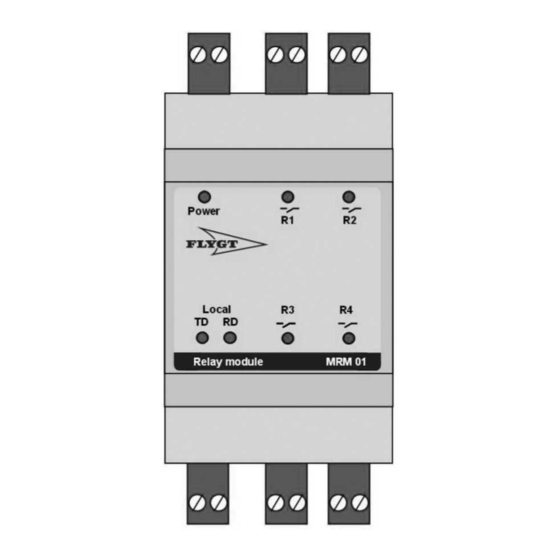
7 Technical Reference 7.6 The LED functions Number LED Function Description Power Power and Blinking = communication error with the MAS base unit communication Lit = power is on and communication with the MAS base unit is indication established Receive data RS-485 or Modbus communication with MAS base unit Transmit data R1–R4... - Page 20 For more information on how Xylem can help you, go to xyleminc.com Refer to www.xylemwatersolutions.com/contacts/ for contact details of your local sales and service representative.