Table of Contents
Advertisement
Quick Links
Advertisement
Table of Contents

Subscribe to Our Youtube Channel
Related Manuals for Arcteq AQ-S214


Summary of Contents for Arcteq AQ-S214
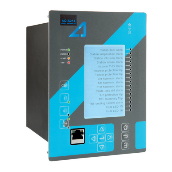
- Page 1 AQ-S214 Alarm and Indication IED Instruction manual...
-
Page 2: Table Of Contents
6.3 Real-time measurements to communication................. 87 7 Connections and applic 7 Connections and applica a tion examples tion examples....................................90 7.1 Connections of AQ-S214..................... 90 8 Construction and installa 8 Construction and installation tion ..........................................93 8.1 Construction........................93 8.2 CPU module ........................ - Page 3 A A Q Q -S214 -S214 Instruction manual Version: 2.04 9.1.1 CPU & Power supply ....................111 9.1.1.1 Auxiliary voltage..................111 9.1.1.2 CPU communication ports................111 9.1.1.3 CPU digital inputs ..................112 9.1.1.4 CPU digital outputs..................113 9.1.2 Option cards ......................114 9.1.2.1 Digital input module ..................
- Page 4 Nothing contained in this document shall increase the liability or extend the warranty obligations of the manufacturer Arcteq Relays Ltd. The manufacturer expressly disclaims any and all liability for any damages and/or losses caused due to a failure to comply with the instructions contained herein or caused by persons who do not fulfil the aforementioned requirements.
- Page 5 A A Q Q -S214 -S214 Instruction manual Version: 2.04 Copyright Copyright © Arcteq Relays Ltd. 2021. All rights reserved.
-
Page 6: Document Inf
A A Q Q -S214 -S214 Instruction manual Version: 2.04 1 Document information 1.1 Version 2 revision notes Table. 1.1 - 1. Version 2 revision notes Revision 2.00 Date 6.6.2019 - New more consistent look. - Improved descriptions generally in many chapters. - Improved readability of a lot of drawings and images. -
Page 7: Version 1 Revision Notes
- Improvements to many drawings and formula images. - Improved and updated IED user interface display images. - AQ-S214 Functions included list Added: Indicator objects. - Added inches to Dimensions and installation chapter. - Added raising frames, wall mounting bracket, combiflex frame to order code. - Page 8 A A Q Q -S214 -S214 Instruction manual Version: 2.04 Date 30.8.2016 Changes - Added password set up guide (previously only in AQtivate user guide) Revision 1.05 Date 10.2.2017 Added Programmable Control Switch and Indicator Object descriptions Changes Order Code updated Revision 1.06 Date...
-
Page 9: Abbr Bbre E Via Viations Tions
A A Q Q -S214 -S214 Instruction manual Version: 2.04 2 Abbreviations AI – Analog input AR – Auto-recloser ASDU – Application service data unit AVR – Automatic voltage regulator BCD – Binary-coded decimal CB – Circuit breaker CBFP – Circuit breaker failure protection CLPU –... - Page 10 A A Q Q -S214 -S214 Instruction manual Version: 2.04 IGBT – Insulated-gate bipolar transistor I/O – Input and output IRIG-B – Inter-range instruction group, timecode B LCD – Liquid-crystal display LED – Light emitting diode LV – Low voltage NC –...
-
Page 11: General
Version: 2.04 3 General The AQ-S214 alarm and indication unit is a member of the AQ-200 product line. The hardware and software are modular: the hardware modules are assembled and configured according to the application's I/O requirements and the software determines the available functions. This manual describes the specific application of the AQ-S214 alarm and indication unit. -
Page 12: Ied User Interface Erface
A A Q Q -S214 -S214 Instruction manual Version: 2.04 4 IED user interface 4.1 Panel structure The user interface section of an AQ-200 series device is divided into two user interface sections: one for the hardware and the other for the software. You can access the software interface either through the front panel or through the AQtivate freeware software suite. -
Page 13: Mimic And Main Menu
Home button switches between the quick display carousel and the main display with the five (5) main configuration menus. The AQ-S214 alarm and indication IED has the following five configuration menus: General , Control, Communication , Transducers and Monitoring . You can switch between these menus by using the four navigational arrow keys and confirming your selection with the E E nt nter er button in the middle. -
Page 14: Navigation In The Main Configuration Menus
A A Q Q -S214 -S214 Instruction manual Version: 2.04 4.2.2 Navigation in the main configuration menus All the settings in this device have been divided into the following five (5) main configuration menus: • General • Control • Communication •... - Page 15 A A Q Q -S214 -S214 Instruction manual Version: 2.04 Device info Figure. 4.3 - 5. Device info. Table. 4.3 - 3. Parameters and indications in the General menu. Name Range Step Default Description Device name Unitname The file name uses these fields when loading the .aqs configuration file from the AQ-200 unit.
- Page 16 A A Q Q -S214 -S214 Instruction manual Version: 2.04 Name Range Step Default Description 0: User defined 1: English 2: Finnish Changes the language of the parameter descriptions in 3: Swedish the HMI. If the language has been set to "Other" in the Language 4: Spanish 1: English...
-
Page 17: Control Menu
A A Q Q -S214 -S214 Instruction manual Version: 2.04 4.4 Control menu Main menu The Control main menu includes submenus (see the image above) for enabling the various control functions and objects ( Controls enabled ), for enabling and controlling the setting groups ( Setting groups) , for configuring the objects ( Objects) , for setting the various control functions ( Control functions) , and for configuring the inputs and outputs ( Device I/O) . - Page 18 A A Q Q -S214 -S214 Instruction manual Version: 2.04 Setting groups Figure. 4.4 - 8. Setting groups submenu. The Setting groups submenu displays all the information related to setting group changing, such as the following: • A A ctiv ctive se e set t ting gr ting group...
- Page 19 A A Q Q -S214 -S214 Instruction manual Version: 2.04 Objects Figure. 4.4 - 10. Objects submenu. Each activated object is visible in the Objects submenu. By default all objects are disabled unless specifically activated in the Controls → Controls enabled submenu. Each active object has four sections in their submenus: "Settings", "Application control"...
- Page 20 A A Q Q -S214 -S214 Instruction manual Version: 2.04 • L L oc ocal/R al/Remo emot t e sta e stat t us us: control access may be set to Local or Remote (Local by default; please note that when local control is enabled, the object cannot be controlled through the bus and vice versa).
- Page 21 A A Q Q -S214 -S214 Instruction manual Version: 2.04 Figure. 4.4 - 12. Application control section. You can connect object statuses directly to specific physical outputs in the "Signal connections" subsection ( Control → Application control ). A status can be connected to output relays, as well as to user-configurable LEDs.
- Page 22 A A Q Q -S214 -S214 Instruction manual Version: 2.04 The "Registers"section stores the function's specific fault data. There are twelve (12) registers, and each of them includes data such as opening and closing times, command types and request failures. The data included in the register depend on the protection function.
- Page 23 A A Q Q -S214 -S214 Instruction manual Version: 2.04 Each control function that has been activated is listed in the Control functions submenu (see the middle image above). This submenu includes the following sections: "Info", "Settings", "Registers", "I/O" and "Events".
- Page 24 A A Q Q -S214 -S214 Instruction manual Version: 2.04 The stage settings vary depending on which control function they are a part of. By default only one setting group of the eight available setting groups is activated. You can enable more groups in the Control →...
- Page 25 A A Q Q -S214 -S214 Instruction manual Version: 2.04 Figure. 4.4 - 19. I/O section. The "I/O" section is divided into two subsections: "Direct output control" and "Blocking input control". In "Direct output control" you can connect the stage's signals to physical outputs, either to an output relay or an LED (START or TRIP LEDs or one of the 16 user configurable LEDs).
- Page 26 A A Q Q -S214 -S214 Instruction manual Version: 2.04 Figure. 4.4 - 20. Events section. You can mask on and mask off events related to an object's stage in "Event mask". By default all events are masked off. You can activate the desired events by masking them ("x"). Please remember to save your maskings by confirming the changes with the check mark icon.
- Page 27 A A Q Q -S214 -S214 Instruction manual Version: 2.04 Figure. 4.4 - 22. Digital input section. All settings related to digital inputs can be found in the "Digital inputs" section. The "Digital inputs settings" subsection includes various settings for the inputs: the polarity selection determines whether the input is Normal Open (NO) or Normal Closed (NC) as well as the activation threshold voltage (16…200 V AC/DC, step 0.1 V) and release threshold voltage (10…200 V AC/DC, step 0.1 V) for each available input.
- Page 28 A A Q Q -S214 -S214 Instruction manual Version: 2.04 The "Digital outputs settings" subsection lets you select the polarity for each output; they can be either Normal Open (NO) or Normal Closed (NC). The default polarity is Normal Open. The operational delay of an output contact is approximately 5 ms.
- Page 29 A A Q Q -S214 -S214 Instruction manual Version: 2.04 Figure. 4.4 - 25. Device I/O matrix section. Through the "Device I/O matrix" section you can connect digital inputs, logical outputs, protection stage status signals (START, TRIP, BLOCKED, etc.), object status signals and many other binary signals to output relays, or to LEDs configured by the used.
- Page 30 A A Q Q -S214 -S214 Instruction manual Version: 2.04 Figure. 4.4 - 27. Programmable mimic indicators section Programmable mimic indicators can be placed into the mimic to display a text based on the status of a given binary signal (digital input, logical signal, status of function start/tripped/blocked signals etc.). When configuring the mimic with the AQtivate setting tool, it is possible to set a text to be shown when an input signal is ON and a separate text for when the signal is OFF.
-
Page 31: Communication Menu
A A Q Q -S214 -S214 Instruction manual Version: 2.04 GOOSE inputs are mainly used for controlling purposes and in conjunction with the IEC 61850 communication protocol. There are 64 GOOSE inputs signal status bits, and their status can be either 0 or 1. - Page 32 A A Q Q -S214 -S214 Instruction manual Version: 2.04 Connections Figure. 4.5 - 29. View of the Connections submenu. The Connections submenu offers the following bits of information and settings: ETHERNET ETHERNET This section defines the IP settings for the ethernet port in the back panel of the unit. •...
-
Page 33: Monitoring Menu
A A Q Q -S214 -S214 Instruction manual Version: 2.04 Protocols Figure. 4.5 - 30. View of the Protocols submenu. The Protocols submenu offers access to the various communication protocol configuration menus. Some of the communication protocols use serial communication and some use Ethernet communication. - Page 34 A A Q Q -S214 -S214 Instruction manual Version: 2.04 Figure. 4.6 - 31. Monitoring menu view. Monitors enabled Figure. 4.6 - 32. Monitors enabled submenu. You can activate the selected monitor functions in the Monitors enabled submenu. By default all the control functions are disabled.
- Page 35 A A Q Q -S214 -S214 Instruction manual Version: 2.04 Monitor functions Figure. 4.6 - 33. Monitor function view. Configuring monitor functions is very similar to configuring protection and control stages. They, too, have the five sections that display information ("Info"), set the parameters ("Settings"), show the inputs and outputs ("I/O") and present the events and registers ("Events"...
- Page 36 A A Q Q -S214 -S214 Instruction manual Version: 2.04 • "Clear all records", "Clear newest record" and "Clear oldest record" allows the clearing of all, the latest, or the oldest recording. • "Max. amount of recordings" displays the maximum number of recordings; depends on the number of channels, the sample rate and the legnth of the file.
-
Page 37: Configuring User Levels And Their Passwords
A A Q Q -S214 -S214 Instruction manual Version: 2.04 Device diagnostics Figure. 4.6 - 35. Device diagnostics submenu. The Device Diagnostics submenu gives a detailed feedback of the device's current condition. It also shows whether option cards have been installed correctly without problems. If you see something out of the ordinary in the Device diagnostics submenu and cannot reset it, please contact the closest representative of the manufacturer or the manufacturer of the device itself. - Page 38 A A Q Q -S214 -S214 Instruction manual Version: 2.04 You can set a new password for a user level by selecting the key icon next to the user level's name. After this you can lock the user level by pressing the R R e e t t urn urn key while the lock is selected.
- Page 39 A A Q Q -S214 -S214 Instruction manual Version: 2.04 NOTE! Any user level with a password automatically locks itself after half an hour (30 minutes) of inactivity.
-
Page 40: Functions Unctions
5 Functions 5.1 Alarming function Signal alarming is the main feature of AQ-S214 Alarming IEDs. The alarming unit has 64 alarms the user can set. The user defines each alarm description and activating signal. These settings are controlled in the Alarm settings menu ( Control → Device I/O → Alarm settings ). - Page 41 A A Q Q -S214 -S214 Instruction manual Version: 2.04 Figure. 5.1 - 38. Digital inputs assigned as alarm activating signals. The user can assign digital inputs or logical outputs into alarms by clicking on the matrix. When the matrix is done, it must be sent to the relay for the changes to take effect ( Commands → Write to relay →...
- Page 42 A A Q Q -S214 -S214 Instruction manual Version: 2.04 Example of an alarm activation and clearing situation Figure. 5.1 - 39. Example situation of an alarm text and LED activation/clearing. In this example Digital Inputs 1 and 2 activate Alarm Texts 1 and 2. The LEDs next to the texts are also lit up as long as the digital inputs are on.
- Page 43 Buzzer activation and deactivation AQ-S214 and AQ-S254 Alarming IEDs do not have an integrated buzzer. However, if an alarming buzzer is needed it is possible to connect an exteral buzzer. It is activated by one of the output relays of the IED.
- Page 44 A A Q Q -S214 -S214 Instruction manual Version: 2.04 Table. 5.1 - 5. Event codes. Event number Event channel Event block name Event code Description ALARM1 Alarm 1 ON ALARM1 Alarm 1 OFF ALARM1 Alarm 2 ON ALARM1 Alarm 2 OFF ALARM1 Alarm 3 ON ALARM1...
- Page 45 A A Q Q -S214 -S214 Instruction manual Version: 2.04 Event number Event channel Event block name Event code Description ALARM1 Alarm 19 OFF ALARM1 Alarm 20 ON ALARM1 Alarm 20 OFF ALARM1 Alarm 21 ON ALARM1 Alarm 21 OFF ALARM1 Alarm 22 ON ALARM1...
- Page 46 A A Q Q -S214 -S214 Instruction manual Version: 2.04 Event number Event channel Event block name Event code Description ALARM2 Alarm 38 OFF ALARM2 Alarm 39 ON ALARM2 Alarm 39 OFF ALARM2 Alarm 40 ON ALARM2 Alarm 40 OFF ALARM2 Alarm 41 ON ALARM2...
-
Page 47: Control Functions
A A Q Q -S214 -S214 Instruction manual Version: 2.04 Event number Event channel Event block name Event code Description ALARM2 Alarm 57 OFF ALARM2 Alarm 58 ON ALARM2 Alarm 58 OFF ALARM2 Alarm 59 ON ALARM2 Alarm 59 OFF ALARM2 Alarm 60 ON ALARM2... - Page 48 A A Q Q -S214 -S214 Instruction manual Version: 2.04 Figure. 5.2.1 - 41. Simplified function block diagram of the setting group selection function. Setting group selection can be applied to each of the setting groups individually by activating one of the various internal logic inputs and connected digital inputs.
- Page 49 A A Q Q -S214 -S214 Instruction manual Version: 2.04 Settings and signals The settings of the setting group control function include the active setting group selection, the forced setting group selection, the enabling (or disabling) of the forced change, the selection of the number of active setting groups in the application, as well as the selection of the setting group changed remotely.
- Page 50 A A Q Q -S214 -S214 Instruction manual Version: 2.04 Name Range Step Default Description 0: Not Setting The selection of Setting group 2 ("SG2"). Has the second highest priority input in setting active 0: Not group group control. Can be controlled with pulses or static signals. If static signal active control is applied, no requests with a lower priority than SG1 will be processed.
- Page 51 A A Q Q -S214 -S214 Instruction manual Version: 2.04 Figure. 5.2.1 - 43. Setting group control – one-wire connection from Petersen coil status. Depending on the application's requirements, the setting group control can be applied either with a one-wire connection or with a two-wire connection by monitoring the state of the Petersen coil connection.
- Page 52 A A Q Q -S214 -S214 Instruction manual Version: 2.04 Figure. 5.2.1 - 44. Setting group control – two-wire connection from Petersen coil status.
- Page 53 A A Q Q -S214 -S214 Instruction manual Version: 2.04 Figure. 5.2.1 - 45. Setting group control – two-wire connection from Petersen coil status with additional logic. The images above depict a two-wire connection from the Petersen coil: the two images at the top show a direct connection, while the two images on the bottom include additional logic.
- Page 54 A A Q Q -S214 -S214 Instruction manual Version: 2.04 Figure. 5.2.1 - 46. Entirely application-controlled setting group change with the cold load pick-up function. In these examples the cold load pick-up function's output is used for the automatic setting group change.
- Page 55 A A Q Q -S214 -S214 Instruction manual Version: 2.04 Event number Event channel Event block name Event code Description 4168 SG6 Enabled 4169 SG6 Disabled 4170 SG7 Enabled 4171 SG7 Disabled 4172 SG8 Enabled 4173 SG8 Disabled 4174 SG1 Request ON 4175 SG1 Request OFF 4176...
-
Page 56: Object Control And Monitoring
A A Q Q -S214 -S214 Instruction manual Version: 2.04 Event number Event channel Event block name Event code Description 4206 SG3 Active ON 4207 SG3 Active OFF 4208 SG4 Active ON 4209 SG4 Active OFF 4210 SG5 Active ON 4211 SG5 Active OFF 4212... - Page 57 A A Q Q -S214 -S214 Instruction manual Version: 2.04 The function generates general time stamped ON/OFF events to the common event buffer from each of the two (2) output signals as well as several operational event signals. The time stamp resolution is 1 ms.
- Page 58 A A Q Q -S214 -S214 Instruction manual Version: 2.04 Name Range Step Default Description 0: Open Blocked 1: Open Allowed 2: Close Additional Blocked status 3: Close Displays additional information about the status of the object. information Allowed 4: Object Ready 5: Object Not Ready 6: Sync Ok...
- Page 59 A A Q Q -S214 -S214 Instruction manual Version: 2.04 Table. 5.2.2 - 11. I/O. Signal Range Description Digital input or other logical Objectx Open input A link to a physical digital input. The monitored object's OPEN status. "1" refers signal selected ("Objectx Open Status to the active open state of the monitored object.
- Page 60 A A Q Q -S214 -S214 Instruction manual Version: 2.04 Name Range Step Default Description Maximum Open Determines the maximum length for a Open pulse from the output relay to the 0.02…500.00 0.02 command 0.2 s controlled object. If the object operates faster than this set time, the control pulse pulse is reset and a status change is detected.
- Page 61 A A Q Q -S214 -S214 Instruction manual Version: 2.04 Figure. 5.2.2 - 48. Example of an interlock application. In order for the blocking signal to be received on time, it has to reach the function 5 ms before the control command.
- Page 62 A A Q Q -S214 -S214 Instruction manual Version: 2.04 Table. 5.2.2 - 14. Event codes of the OBJ function instances 1 – 10. Event Number Event channel Event block name Event Code Description 2944 OBJ1 Object Intermediate 2945 OBJ1 Object Open 2946 OBJ1...
- Page 63 A A Q Q -S214 -S214 Instruction manual Version: 2.04 Event Number Event channel Event block name Event Code Description 3017 OBJ2 Open Request OFF 3018 OBJ2 Open Command ON 3019 OBJ2 Open Command OFF 3020 OBJ2 Close Request ON 3021 OBJ2 Close Request OFF...
- Page 64 A A Q Q -S214 -S214 Instruction manual Version: 2.04 Event Number Event channel Event block name Event Code Description 3091 OBJ3 Close Blocked OFF 3092 OBJ3 Object Ready 3093 OBJ3 Object Not Ready 3094 OBJ3 Sync Ok 3095 OBJ3 Sync Not Ok 3096 OBJ3...
- Page 65 A A Q Q -S214 -S214 Instruction manual Version: 2.04 Event Number Event channel Event block name Event Code Description 3201 OBJ5 Object Open 3202 OBJ5 Object Close 3203 OBJ5 Object Bad 3204 OBJ5 WD Intermediate 3205 OBJ5 WD Out 3206 OBJ5 WD In...
- Page 66 A A Q Q -S214 -S214 Instruction manual Version: 2.04 Event Number Event channel Event block name Event Code Description 9611 OBJ6 Open Command OFF 9612 OBJ6 Close Request ON 9613 OBJ6 Close Request OFF 9614 OBJ6 Close Command ON 9615 OBJ6 Close Command OFF...
- Page 67 A A Q Q -S214 -S214 Instruction manual Version: 2.04 Event Number Event channel Event block name Event Code Description 9685 OBJ7 Object Not Ready 9686 OBJ7 Sync Ok 9687 OBJ7 Sync Not Ok 9688 OBJ7 Open Command Fail 9689 OBJ7 Close Command Fail 9690...
- Page 68 A A Q Q -S214 -S214 Instruction manual Version: 2.04 Event Number Event channel Event block name Event Code Description 9795 OBJ9 Object Bad 9796 OBJ9 WD Intermediate 9797 OBJ9 WD Out 9798 OBJ9 WD In 9799 OBJ9 WD Bad 9800 OBJ9 Open Request ON...
-
Page 69: Indicator Object Monitoring
A A Q Q -S214 -S214 Instruction manual Version: 2.04 Event Number Event channel Event block name Event Code Description 9869 OBJ10 Close Request OFF 9870 OBJ10 Close Command ON 9871 OBJ10 Close Command OFF 9872 OBJ10 Open Blocked ON 9873 OBJ10 Open Blocked OFF... - Page 70 A A Q Q -S214 -S214 Instruction manual Version: 2.04 The outputs of the function are the monitored indicator statuses (Open, Close, Intermediate and Bad). The setting parameters are static inputs for the function, which can only be changed by the use in the function's setup phase.
-
Page 71: Milliampere Output Control
A A Q Q -S214 -S214 Instruction manual Version: 2.04 Event Number Event channel Event block name Event Code Description 6721 CIN2 Open 6722 CIN2 Close 6723 CIN2 6784 CIN3 Intermediate 6785 CIN3 Open 6786 CIN3 Close 6787 CIN3 6848 CIN4 Intermediate 6849... - Page 72 A A Q Q -S214 -S214 Instruction manual Version: 2.04 Table. 5.2.4 - 19. Main settings (output channels). Name Range Default Description Enable mA output channels 1 and 2 mA option Enables and disables the outputs of the mA output Disabled card 1 Disabled...
-
Page 73: Programmable Control Switch
A A Q Q -S214 -S214 Instruction manual Version: 2.04 Table. 5.2.4 - 21. Hardware indications. Name Range Step Description Hardware in mA output channels 1...4 0: None 1: Slot A 2: Slot B 3: Slot C Indicates the option card slot where the mA output card is located. Hardware in mA output channels 5...8 4: Slot D 5: Slot E... -
Page 74: Analog Input Scaling Curves
A A Q Q -S214 -S214 Instruction manual Version: 2.04 Events The programmable control switch function (abbreviated "PCS" in event block names) generates events from status changes. The user can select which event messages are stored in the main event buffer: ON, OFF, or both. - Page 75 A A Q Q -S214 -S214 Instruction manual Version: 2.04 Name Range Step Default Description 0: S7 mA Input 1: S8 mA Input 2: S15 mA Input 3: S16 mA Input 4: DI1 Voltage 23: DI20 Voltage 0: S7 Curve 1...4 input 24: RTD S1 Defines the measurement used by scaling curve.
- Page 76 A A Q Q -S214 -S214 Instruction manual Version: 2.04 When the curve signal is out of range, it activates the "ASC1...4 input out of range" signal, which can be used inside logic or with other relay functions. The signal can be assigned directly to an output relay or to an LED in the I/O matrix.
-
Page 77: Logical Outputs
A A Q Q -S214 -S214 Instruction manual Version: 2.04 5.2.7 Logical outputs Logical outputs are used for sending binary signals out from a logic that has been built in the logic editor. Logical signals can be used for blocking functions, changing setting groups, controlling digital outputs, activating LEDs, etc. - Page 78 A A Q Q -S214 -S214 Instruction manual Version: 2.04 A logical input pulse can also be extended by connecting a DELAY-low gate to a logical output, as has been done in the example figure below. Figure. 5.2.8 - 53. Extending a logical input pulse.
-
Page 79: Sy Y St Stem Int 6 S Em Integra Egration Tion
A A Q Q -S214 -S214 Instruction manual Version: 2.04 6 System integration 6.1 Communication protocols 6.1.1 NTP When enabled, the NTP (Network Time Protocol) service can use external time sources to synchronize the device's system time. The NTP client service uses an Ethernet connection to connect to the NTP time server. -
Page 80: Modbus/Tcp And Modbus/Rtu
A A Q Q -S214 -S214 Instruction manual Version: 2.04 6.1.2 Modbus/TCP and Modbus/RTU The device supports both Modbus/TCP and Modbus/RTU communication. Modbus/TCP uses the Ethernet connection to communicate with Modbus/TCP clients. Modbus/RTU is a serial protocol that can be selected for the available serial ports. The following Modbus function types are supported: •... -
Page 81: Modbus I/O
AQ-25x frame units support both Edition 1 and 2 of IEC61850. The following services are supported by IEC 61850 in Arcteq devices: • Up to six data sets (predefined data sets can be edited with the IEC 61850 tool in AQtivate) •... - Page 82 The device's current IEC 61850 setup can be viewed and edited with the IEC61850 tool ( Tools → Communication → IEC 61850 ). By browsing the 61850 tree one can see the full list of available logical nodes in the Arcteq implementation. Settings.
-
Page 83: Goose
(slave) station. The IEC 103 protocol can be selected for the serial ports that are available in the device. A primary (master) station can then communicate with the Arcteq device and receive information by polling from the slave device. The transfer of disturbance recordings is not supported. -
Page 84: Dnp3
DNP3 slave is compliant with the DNP3 subset (level) 2, but it also contains some functionalities of the higher levels. For detailed information please refer to the DNP3 Device Profile document (www.arcteq.fi/downloads/ → AQ-200 series → Resources). Settings The following table describes the DNP3 setting parameters. - Page 85 A A Q Q -S214 -S214 Instruction manual Version: 2.04 Name Range Default Description 0: Var 1 Group 4 variation (DBI change) 1: Var 2 Selects the variation of the double point signal. 1: Var 2 0: Var 1 1: Var 2 Group 20 variation (CNTR) 0: Var 1 Selects the variation of the control signal.
-
Page 86: Iec 101/104
IEC 104 protocol uses Ethernet communication. The IEC 101/104 implementation works as a slave in the unbalanced mode. For detailed information please refer to the IEC 101/104 interoperability document (www.arcteq.fi/ downloads/ → AQ-200 series → Resources → "AQ-200 IEC101 & IEC104 interoperability"). - Page 87 A A Q Q -S214 -S214 Instruction manual Version: 2.04 • Current • Residual current • Voltage • Residual voltage • Angle The range is the same for all of the scaling coefficients. By default, there is no scaling. • No scaling •...
-
Page 88: Spa
A A Q Q -S214 -S214 Instruction manual Version: 2.04 6.1.9 SPA The device can act as a SPA slave. SPA can be selected as the communication protocol for the COM B port (RS-485 port in the CPU module). When the device includes a serial RS-232 card connector, the SPA protocol can also be selected as the communication protocol for the COM E and COM F ports. - Page 89 A A Q Q -S214 -S214 Instruction manual Version: 2.04 Measurable values Function block uses analog current and voltage measurement values. The relay uses these values as the basis when it calculates the primary and secondary values of currents, voltages, powers, impedances and other values.
- Page 90 A A Q Q -S214 -S214 Instruction manual Version: 2.04 Signals Description Z12Ang, Z23Ang, Z31Ang, Phase-to-phase and phase-to-neutral impedance angles. ZL1Ang, ZL2Ang, ZL3Ang Rseq, Xseq, Zseq Positive sequence resistance, reactance and impedance values and angles. RseqAng, XseqAng, ZseqAng GL1, GL2, GL3, G0 BL1, BL2, BL3, B0 Conductances, susceptances and admittances.
-
Page 91: Connections Of Aq-S214
A A Q Q -S214 -S214 Instruction manual Version: 2.04 7 Connections and application examples 7.1 Connections of AQ-S214 Figure. 7.1 - 54. AQ-S214 variant without add-on modules. - Page 92 A A Q Q -S214 -S214 Instruction manual Version: 2.04 Figure. 7.1 - 55. AQ-S214 variant with digital input and output modules.
- Page 93 A A Q Q -S214 -S214 Instruction manual Version: 2.04 Figure. 7.1 - 56. AQ-S214 application example.
-
Page 94: Construction And Installa
In field upgrades, therefore, the add-on module must be ordered from Arcteq Relays Ltd. or its representative who can then provide the module with its corresponding unlocking code to allow the device to operate correctly once the hardware configuration has been upgraded. - Page 95 A A Q Q -S214 -S214 Instruction manual Version: 2.04 When an I/O module is inserted into the device, the module location affects the naming of the I/O. The I/O scanning order in the start-up sequence is as follows: the CPU module I/O, Slot A, Slot B, Slot C, Slot D, Slot E, Slot F.
- Page 96 A A Q Q -S214 -S214 Instruction manual Version: 2.04 3. Scan Scans Slot B, and moves to the next slot if Slot B is empty. If the scan finds an 8DI module, it reserves the designations "DI4", "DI5", "DI6", "DI7", "DI8", "DI9", "DI10" and "DI11" to this slot. If Slot A also has an 8DI module (and therefore has already reserved these designations), the device reserves the designations "DI12", "DI13", "DI14", "DI15", "DI16", "DI17", "DI18"...
-
Page 97: Cpu Module
A A Q Q -S214 -S214 Instruction manual Version: 2.04 8.2 CPU module Figure. 8.2 - 59. CPU module. Module connectors Table. 8.2 - 46. Module connector descriptions. Connector Description Communication port A, or the RJ-45 port. Used for the setting tool connection and for IEC 61850, Modbus/ COM A TCP, IEC 104, DNP3 and station bus communications. - Page 98 A A Q Q -S214 -S214 Instruction manual Version: 2.04 Connector Description System fault's output relay, with a changeover contact. Pins 16 and 17 are closed when the unit has a system X 16:17:18 fault or is powered OFF. Pins 16 and 18 are closed when the unit is powered ON and there is no system fault. Power supply IN.
-
Page 99: Digital Input Module (Optional)
A A Q Q -S214 -S214 Instruction manual Version: 2.04 8.3 Digital input module (optional) Figure. 8.3 - 60. Digital input module (DI8) with eight add-on digital inputs. Description (x = the number of digital inputs in other modules that preceed this one in the Connector configuration) DIx + 1... - Page 100 A A Q Q -S214 -S214 Instruction manual Version: 2.04 Setting up the activation and release delays The settings described in the table below can be found at Control → Device I/O → Digital input settings in the relay settings. Table.
-
Page 101: Digital Output Module (Optional)
A A Q Q -S214 -S214 Instruction manual Version: 2.04 Figure. 8.3 - 61. Digital input state when energizing and de-energizing the digital input channels. Digital input voltage measurements Digital input option card channels measure voltage on each channel. The measured voltage can be seen at Control →... -
Page 102: Rtd Input Module (Optional)
A A Q Q -S214 -S214 Instruction manual Version: 2.04 Connector Description X 5–6 OUTx + 3 (1 and 2 pole NO) X 7–8 OUTx + 4 (1 and 2 pole NO) X 9–10 OUTx + 5 (1 and 2 pole NO) The DO5 module is an add-on module with five (5) digital outputs. -
Page 103: Serial Rs-232 Communication Module (Optional)
A A Q Q -S214 -S214 Instruction manual Version: 2.04 Figure. 8.5 - 64. Different sensor types and their connections. 8.6 Serial RS-232 communication module (optional) Figure. 8.6 - 65. Serial RS-232 module connectors. Connector Name Description • Serial-based communications •... -
Page 104: Lc 100 Mbps Ethernet Communication Module (Optional)
A A Q Q -S214 -S214 Instruction manual Version: 2.04 Connector Name Description COM F – +24 V input Optional external auxiliary voltage for serial fiber Pin 1 COM F – Optional external auxiliary voltage for serial fiber Pin 2 COM F –... -
Page 105: Double St 100 Mbps Ethernet Communication Module (Optional)
A A Q Q -S214 -S214 Instruction manual Version: 2.04 Connector Description • Communication port C, LC fiber connector. • 62.5/125 μm or 50/125 μm multimode (glass). COM C: • Wavelength 1300 nm. • Communication port D, LC fiber connector. •... - Page 106 A A Q Q -S214 -S214 Instruction manual Version: 2.04 This option cards supports redundant ring configuration and multidrop configurations. Redundant communication can be implemented by Ethernet switches that support Rapid Spanning Tree Protocol (RSTP). Please note that each ring can only contain AQ-200 series devices, and any third party devices must be connected to a separate ring.
-
Page 107: Double Rj-45 10/100 Mbps Ethernet Communication Module (Optional)
A A Q Q -S214 -S214 Instruction manual Version: 2.04 Figure. 8.8 - 69. Example of a multidrop configuration. 8.9 Double RJ-45 10/100 Mbps Ethernet communication module (optional) Figure. 8.9 - 70. Double RJ-45 10/100 Mbps Ethernet communication module. Connector Description •... - Page 108 A A Q Q -S214 -S214 Instruction manual Version: 2.04 Connector Description • Two Ethernet ports • RJ-45 connectors RJ-45 connectors • 10BASE-T and 100BASE-TX This option card supports multidrop configurations. For other redundancy options, please refer to the option card "LC 100 Mbps Ethernet communication module".
-
Page 109: Dimensions And Installation
A A Q Q -S214 -S214 Instruction manual Version: 2.04 Figure. 8.9 - 72. Example of a multidrop configuration. 8.10 Dimensions and installation The device can be installed either to a standard 19” rack or to a switchgear panel with cutouts. The desired installation type is defined in the order code. - Page 110 A A Q Q -S214 -S214 Instruction manual Version: 2.04 Figure. 8.10 - 74. Device installation.
- Page 111 A A Q Q -S214 -S214 Instruction manual Version: 2.04 Figure. 8.10 - 75. Panel cutout dimensions and device spacing.
-
Page 112: Technic Echnical Da Al Data Ta
A A Q Q -S214 -S214 Instruction manual Version: 2.04 9 Technical data 9.1 Hardware 9.1.1 CPU & Power supply 9.1.1.1 Auxiliary voltage Table. 9.1.1.1 - 50. Power supply model A Rated values Rated auxiliary voltage 85…265 V (AC/DC) < 7 W Power consumption <... -
Page 113: Cpu Digital Inputs
A A Q Q -S214 -S214 Instruction manual Version: 2.04 Features Data transfer rate 100 MB System integration Cannot be used for system protocols, only for local programming Table. 9.1.1.2 - 53. Rear panel system communication port A. Port Port media Copper Ethernet RJ-45 Number of ports Features... -
Page 114: Cpu Digital Outputs
A A Q Q -S214 -S214 Instruction manual Version: 2.04 Pick-up delay Software settable: 0…1800 s Polarity Software settable: Normally On/Normally Off Current drain 2 mA Terminal block connection Terminal block Phoenix Contact MSTB 2,5/5-ST-5,08 Solid or stranded wire 2.5 mm Maximum wire diameter 9.1.1.4 CPU digital outputs Table. -
Page 115: Option Cards
A A Q Q -S214 -S214 Instruction manual Version: 2.04 9.1.2 Option cards 9.1.2.1 Digital input module Table. 9.1.2.1 - 58. Technical data for the digital input module. Rated values Rated auxiliary voltage 5…265 V (AC/DC) Current drain 2 mA Scanning rate 5 ms Activation/release delay... -
Page 116: Serial Fiber Communication Module
A A Q Q -S214 -S214 Instruction manual Version: 2.04 2/3/4-wire RTD and thermocouple sensors Pt100 or Pt1000 Type K, Type J, Type T and Type S Channels 7 & 8 support mA measurement 9.1.2.4 RS-232 & serial fiber communication module Table. -
Page 117: Functions
A A Q Q -S214 -S214 Instruction manual Version: 2.04 9.2 Functions 9.2.1 Control functions 9.2.1.1 Setting group selection Table. 9.2.1.1 - 64. Technical data for the setting group selection function. Settings and control modes Setting groups 8 independent, control-prioritized setting groups Control scale Common for all installed functions which support setting groups Control mode... - Page 118 A A Q Q -S214 -S214 Instruction manual Version: 2.04 Conducted emissions: 150 kHz…30 MHz EN 60255-26 Ch. 5.2, CISPR 22 Radiated emissions: 30…1 000 MHz EN 60255-26 Ch. 5.1, CISPR 11 Immunity Electrostatic discharge (ESD): Air discharge 15 kV EN 60255-26, IEC 61000-4-2 Contact discharge 8 kV Electrical fast transients (EFT):...
- Page 119 A A Q Q -S214 -S214 Instruction manual Version: 2.04 Table. 9.3 - 70. Environmental conditions. IP classes IP54 (front) Casing protection class IP21 (rear) Temperature ranges Ambient service temperature range –35…+70 °C Transport and storage temperature range –40…+70 °C Other Altitude <2000 m...
-
Page 120: Ordering Inf Dering Informa Ormation Tion
A A Q Q -S214 -S214 Instruction manual Version: 2.04 10 Ordering information Accessories Order code der code Descrip Description tion Not t e e Manufact Manufactur urer er External 6-channel 2 or 3 wires RTD Input module, pre- Requires an external power Advanced Co. - Page 121 A A Q Q -S214 -S214 Instruction manual Version: 2.04 AQX033 Raising frame 87 mm Arcteq Ltd. AQX070 Raising frame 40 mm Arcteq Ltd. AQX069 Combiflex frame Arcteq Ltd. AQX097 Wall mounting bracket Arcteq Ltd.
-
Page 122: Contact And R Ence Informa Ormation Tion
A A Q Q -S214 -S214 Instruction manual Version: 2.04 11 Contact and reference information Manufacturer Arcteq Relays Ltd. Visiting and postal address Kvartsikatu 2 A 1 65300 Vaasa, Finland Contacts Phone: +358 10 3221 370 Fax: +358 10 3221 389 Website (general): arcteq.fi...
Need help?
Do you have a question about the AQ-S214 and is the answer not in the manual?
Questions and answers