Table of Contents
Advertisement
Quick Links
WARRANTY AND DISCLAIMER
DIGITAL DELAY ELECTRONICS, INC. WARRANTS THE PRODUCTS IT
MANUFACTURES AGAINST DEFECTS IN MATERIALS AND WORKMANSHIP FOR A
PERIOD LIMITED TO 1 YEAR FROM THE DATE OF SHIPMENT, PROVIDED THE
PRODUCTS HAVE BEEN STORED, HANDLED, INSTALLED, AND USED UNDER
PROPER CONDITIONS.
The company's liability under this limited warranty shall extend only to the repair or
replacement of a defective product, at the company's option. Digital Delay Inc. and Digital
Delay Electronics, Inc. disclaims all liability for any affirmation, promise, or representation
with respect to the products.
The customer agrees to hold Digital Delay Inc. and Digital Delay Electronics, Inc
harmless from, defend, and indemnify Digital Delay Inc. and Digital Delay Electronics, Inc
against damages, claims, and expenses arising out of subsequent sales of or use of Digital Delay
Inc. and Digital Delay Electronics, Inc products, or products containing components
manufactured by Digital Delay Electronics, Inc. and based upon personal injuries, deaths,
property damage, lost profits, and other matters which BUYER, its employees, or sub-
contractors are or may be to any extent liable, including without limitation, penalties imposed
by the Consumer Product Safety Act (P.L. 92-573) and liability imposed upon any person
pursuant to the Magnuson-Moss Warranty Act (P.L. 93-637), as now in effect or as amended
hereafter.
No warranties expressed or implied, are created with respect to the company's products
except those expressly contained herein. The customer acknowledges the disclaimers and
limitations contained and relies on no other warranties or affirmations.
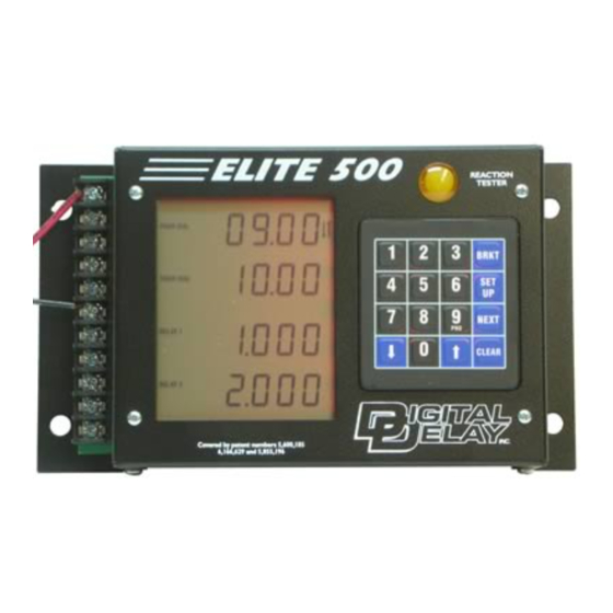
ELITE 500
1
2036 Fillmore Street
Davenport, Ia. 52804
563-324-1046
www.racedigitaldelay.com
Advertisement
Table of Contents

Related Manuals for DIGITAL DELAY ELITE 500

Summary of Contents for DIGITAL DELAY ELITE 500
-
Page 1: Warranty And Disclaimer
Digital Delay Inc. and Digital Delay Electronics, Inc against damages, claims, and expenses arising out of subsequent sales of or use of Digital Delay Inc. and Digital Delay Electronics, Inc products, or products containing components manufactured by Digital Delay Electronics, Inc. -
Page 2: Table Of Contents
Understanding the Line Lock/Multi-Tap Push-button …...……....…………..……… Page 20 Connecting and Understanding a By-pass Push-button…………………………………….Page 20 Connecting two or More Outputs Together………………………………………………... Page 20 Understanding How to Cancel a Timing Cycle using the Clear Key……………………… Page 20 Mounting and Wiring the Elite 500..........………………..... Page 21... -
Page 3: Features And Specifications
Features and Specifications Features: • Microprocessor controlled timing • Discrete I/O (input - output) construction • Retains all numbers even with power disconnected from unit • Large illuminated LCD (liquid crystal display) and keypad for easy reading of information day or night •... -
Page 4: The Terminal Strip
Shift Terminal: Connect the Shift terminal to the shifter solenoid. It is recommended that the wire going from the Elite 500 shift terminal to the shift solenoid be separated from all other wires to eliminate cross talk between the wires. If all wires are bundled together undesirable results may occur. -
Page 5: The Keypad And The Lcd
The Keypad The keypad is made up of numerical and function keys that are used to control the information that is either entered into the unit or shown on the displays. There are six blue function keys they are BRKT, SET UP, NEXT, CLEAR, Up Arrow, and Down Arrow. -
Page 6: Bracket Mode Screens
When the Elite 500 is displaying Screen 1 the Bracket Screen, Your Dial is displayed on line 1, Their Dial is displayed on line 2, Delay 1 is displayed on line 3, and Delay 2 is displayed on line 4. The Elite 500 uses the Dial-ins for two functions, first to see whether to Crossover or not and secondly if Crossing over how much time will be added to Delay 1. -
Page 7: Bracket Mode Settings For Screen
Setting and Understanding the Multi-Tap This new and exclusive feature of the Elite 500 Delay Box was added to subtract large amounts of time from delay 1 with every press of the Multi Tap push-button. This is used when the driver feels they have completely missed the start of the tree. -
Page 8: Bracket Mode Settings For Screen 3
Bracket Mode Settings for Screen 3 When the Elite 500 is displaying Screen 3, the Starting Line Enhancer time is displayed on line 1, the P.T.S.O. time is displayed on line 2, the Push-button Mode and Interrupt time is displayed on line 3, and the S.F.O. Mode is displayed on line 4. Once these settings are set they usually do not have to be changed unless the setup of the vehicle changes or the style of racing. -
Page 9: Setting Push-Button Mode And Interrupt Time
The Elite 500 has two 4 Stage Timers called Timer 1 and Timer 2. All of the settings for Timer 1 are on Screen 4 and all of the settings for Timer 2 are on Screen 5. When the Elite 500 is displaying Screen 4 or 5, the Stage 1 time is displayed on line 1, the Stage 2 time is displayed on line 2, the Stage 3 time is displayed on line 3, and the Stage 4 time is displayed on line 4. -
Page 10: Setting Throttle Modes
The Elite 500 can handle up to five shifts on each pass. The shifts occur in sequence 1 through 5, after the Transbrake releases. When the Elite 500 is displaying Screen 6 the Shift Points are displayed on line 1, the Shift Numbers are displayed on line 2, Multi-shift is displayed on line 3, and Shift Mode is displayed on line 4. -
Page 11: Pro Mode Screens
S.F.O. and the P.T.S.O. settings. However all Bracket Mode settings are retained in memory and will be available when the Elite 500 returns to Bracket Mode. The Pro Mode of the Elite 500 has 5 different screens. While in Pro Mode, the Set Up key is used to move from screen to screen. -
Page 12: Setting The Time Range (Xx.xx Or X.xxx)
Setting the Time Range (xx.xx or x.xxx) The Time Range controls the resolution of the first and second stages times only. The first and second stage times can be set to any number from 0.000 to 9.999 seconds when in “x.xxx” Range and from 00.00 to 99.99 seconds when in “xx.xx” Range. The settings for Pro Timer 1 and for Pro Timer 2 do not have to be the same. -
Page 13: Pro Mode Settings For Screens 2 & 3
The Elite 500 has two Pro Mode 4 Stage Timers called Pro Timer 1 and Pro Timer 2. All of the settings for Pro Timer 1 are on Screen 2 and all of the settings for Pro Timer 2 are on Screen 3. When the Elite 500 is displaying Screen 2 or 3, the Stage 1 time is displayed on line 1, the Stage 2 time is displayed on line 2, the Stage 3 time is displayed on line 3, and the Stage 4 time is displayed on line 4. -
Page 14: Pro Mode Settings For Screen 4
The Pro Mode feature of the Elite 500 was designed especially for vehicles that are used in Pro Light racing. Pro Mode has its own set of screens and settings. Most of these settings are unique to Pro Mode and have no effect on the unit when the Elite 500 is running in Bracket Mode. -
Page 15: The Push-Buttons For Pro Mode
Understanding Bracket Mode When the Elite 500 is in Bracket Mode the Pro Mode is turned off. However all of the settings for the Pro Mode are saved in memory for when you go back to Pro Mode. Bracket Mode has a main screen that displays the Dial-ins and the Delays (you can access this screen by pressing the BRKT key at any time). -
Page 16: Understanding The Tap-Up And Tap-Down Feature
To display the How Late information, repeatedly press the Set Up key until the text “How Late” is displayed on the left side of line 3. When taking two hits at the tree, the How Late feature of the Elite 500 will display which hit at the tree was used to release the Transbrake. -
Page 17: Understanding Push-Button Modes And Interrupt Time
Because the S.F.O. can be used to control the Transbrake solenoid a safety circuit for the S.F.O. had to be designed into the Elite 500. When the S.F.O. mode is set to 3, 4, or 5 the operation of the safety circuit is transparent. When the S.F.O. mode is set to either 1 or 2 the Elite 500 will always work when a push-button is pressed. -
Page 18: How The Programmable Throttle Stop Override Works
Using all twos (22.22) will set the S.L.E. to Pro Mode. When the S.L.E. is set to Pro Mode, the release of the throttle will occur .25 seconds after the Transbrake is engaged. This means that the throttle must be closed using the Tap P.B. before staging. NOTE: Use the Throttle mode for Timer 2, which can only be set while viewing the 4 Stage times for Timer 2 on Screen 5, to change output voltage of the S.F.O. -
Page 19: Understanding The 4 Stage Timer
Once in Reaction Test Mode, press a push-button connected to either P.B. 1 or P.B. 2. After a preset amount of time the bulb on the top of the Elite 500 turns on, at which time the driver releases the push-button being held. On the top line the display will now show the amount of time from when the bulb came on to when the push-button was released, this is the reaction time. -
Page 20: Understanding The Line Lock/Multi-Tap Push-Button
2) To control the Multi-tap when the Transbrake is applied. If the vehicle has Line Lock Solenoids, but the Elite 500 is not going to be used to control the Line Locks at the starting line, it is not necessary to connect either the Line Lock push-button or the Line Lock solenoids to the unit. -
Page 21: Mounting And Wiring The Elite 500
For complete viewing of the large LCD, care should be taken when mounting the unit to make sure that the display is angled towards the driver’s eyes. Before mounting the Elite 500, place the box in the desired location and check the legibility of the display in both day and night conditions.
Need help?
Do you have a question about the ELITE 500 and is the answer not in the manual?
Questions and answers