
Subscribe to Our Youtube Channel
Related Manuals for Illinois Tool Works IJ4000

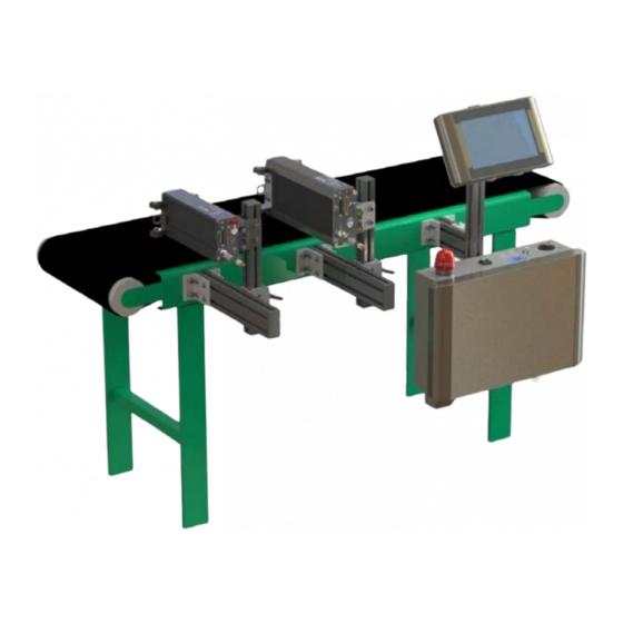
Summary of Contents for Illinois Tool Works IJ4000
- Page 1 Operations Manual IJ4000 Impulse Jet System 5765-018 Revision J 1 Missouri Research Park Drive • St. Charles, MO 63304 • Service Line 1-800-526-2531 Illinois Tool Works Inc © 2021...
- Page 2 The information contained in this manual is correct and accurate at the time of its publication. ITW reserves the right to change or alter any information or technical specifications at any time and without notice. ©2021 Illinois Tool Works Inc. All rights reserved...
- Page 3 IJ4000 System Warranty: The IJ4000 Impulse Jet System, including all components unless otherwise specified, carries a limited warranty. The inks and conditioners used with the IJ4000 Impulse Jet System carry a limited warranty. For all warranty terms and conditions, contact Diagraph an ITW Company for a complete copy of the Limited Warranty...
-
Page 4: Table Of Contents
Step 2: Assemble Print Head onto Bracketry .............................9 Step 3: Adjust Print Head to Substrate ..............................11 Step 4: Install SMART-IDS ..................................12 Step 5: Install IJ4000-HMI Controller ..............................15 Step 6: Electrical Cable Connections ................................16 Step 7: Install Tubing ....................................18 Step 8: Prime Ink Lines ....................................19 Step 9: Priming the Print Head and Testing Print Quality ........................21... - Page 5 Appendix D: InkJet Demo Software for Windows ............................71 Appendix E: Software Interface ..................................71 Appendix F: Part Numbers ....................................72 System ........................................72 Bracketry ........................................73 Fittings and Tubing ....................................74 IJ4000-HMI ......................................74 IJ4000 SMART-IDS ....................................75 Cables ........................................76 Print Head Replacement Parts ..................................76 Consumables ......................................77 Service Parts and Optional Equipment ..............................78...
-
Page 6: Section 1: Safety And Ink Usage
IJ4000 Impulse Jet Section 1: Safety and Ink Usage Section 1: Safety and Ink Usage Following is a list of safety symbols and their meanings, which are found throughout this manual. Pay attention to these symbols where they appear in the manual. -
Page 7: Section 2: Quick Start
System Components: • Bracketry Kit (Item 1) • Print Head (Item 2) • -IDS (Item 3) MART • IJ4000-HMI Controller (Item 4) • Power Cord (not shown) • Serial Cable (not shown) • Tubing (not shown) • Software (not shown) (Ink is not included.) -
Page 8: Step 1: Assemble Bracketry To Conveyor
IJ4000 Impulse Jet Section 2: Quick Start Step 1: Assemble Bracketry to Conveyor NOTE: Mount bracketry as square and as level as possible. PRINT HEAD CONVEYOR MOUNT (5765-246 for 384E Print Head) (5765-253 for 768E Print Head) HMI CONTROLLER /... -
Page 9: Step 2: Assemble Print Head Onto Bracketry
IJ4000 Impulse Jet Section 2: Quick Start Step 2: Assemble Print Head onto Bracketry RETRACTING BRACKET CAN BE MOUNTED ON EITHER SIDE OF PRINT HEAD ROLLER / RETRACTING BRACKET MOUNT FOR 768E PRINT HEAD (5765-253) ROLLER / RETRACTING BRACKET MOUNT FOR... - Page 10 IJ4000 Impulse Jet Section 2: Quick Start Print Head Mounting Limitations Print Head Tilt ± 5° MAX Maximum Print Head Tilt: 768E PRINT HEAD • Clockwise Tilt: 5° • Counterclockwise Tilt: 5° NOTE: Tilt angles are given when looking at the rear of the print head.
-
Page 11: Step 3: Adjust Print Head To Substrate
IJ4000 Impulse Jet Section 2: Quick Start Step 3: Adjust Print Head to Substrate Use the bracket handle to adjust print head vertically. VERTICAL ADJUSTMENT BRACKET HANDLE Loosen the adjustment knobs on the Retracting Bracket to slide the print head toward or away from substrate. -
Page 12: Step 4: Install Smart-Ids
IJ4000 Impulse Jet Section 2: Quick Start Step 4: Install S -IDS MART -IDS MART OPTIONAL FLOOR MOUNT 5765-018 Operations Manual Rev J Page 12... - Page 13 IJ4000 Impulse Jet Section 2: Quick Start Tubing Limitations - Vertical Best Practices • Mount Smart-IDS below the height of the print heads. Conveyor • Do not create service loops or coils 1.5m (5ft) of tubing. (Consult Factory • Minimize length of tubing by cutting...
- Page 14 IJ4000 Impulse Jet Section 2: Quick Start Tubing Limitations - Horizontal 384E Print Heads: 768E Print Heads: 1 Print Head 1 Print Head SMART-IDS 15,2m (50ft) Maximum Total Tubing Length SMART-IDS 12,2m (40ft) Maximum Total Tubing Length 2 Print Heads...
-
Page 15: Step 5: Install Ij4000-Hmi Controller
IJ4000 Impulse Jet Section 2: Quick Start Step 5: Install IJ4000-HMI Controller CONTROLLER 5765-018 Operations Manual Rev J Page 15... -
Page 16: Step 6: Electrical Cable Connections
4. Customer system connections are made inside the HEAD IJ4000-HMI -IDS. (Refer to the following page.) MART CABLES NOTE: It is recommended that the Task 1 Print Head be closest to the IJ4000-HMI. 5. Plug the S -IDS into the appropriate mains MART -IDS MART power outlet. - Page 17 IJ4000 Impulse Jet Section 2: Quick Start SMART-IDS NOTE: In many applications, Photocell and Encoder may be shared from Task 1 to Task 2 PHOTOSENSOR / PRINT HEAD ENCODER CABLES CABLE ENCODER / POWER I/O CABLE FROM INTERNAL CIRCUIT PHOTOSENSOR...
-
Page 18: Step 7: Install Tubing
IJ4000 Impulse Jet Section 2: Quick Start Step 7: Install Tubing REMOVE AND SAVE CAP 4,6mm [15ft] MAX NOTE: Do not attempt plumbing this sys- FILTER tem before all mechanical mounting is VACUUM completed. 1. After mechanical mounting is com-... -
Page 19: Step 8: Prime Ink Lines
IJ4000 Impulse Jet Section 2: Quick Start Step 8: Prime Ink Lines CAUTION: CAUTION • Ensure all vent caps, top and bottom, have been removed from the print head(s) and S -IDS. MART REMOVE • Ensure no tubing is connected to the print heads. - Page 20 IJ4000 Impulse Jet Section 2: Quick Start Confirm the print head(s) are level. The green LED indicates head is level. (384E Print Head is shown.) WHEN UPPER LED IS RED, PRINT HEAD IS POINTED UP TOO FAR WHEN CENTER LED IS...
-
Page 21: Step 9: Priming The Print Head And Testing Print Quality
IJ4000 Impulse Jet Section 2: Quick Start Step 9: Priming the Print Head and Testing Print Quality 1. Ensure caps and plugs (vent, vacuum, and ink inlet) from the rear of the print head 384E PRINT HEAD have been removed and stored (see diagram). - Page 22 IJ4000 Impulse Jet Section 2: Quick Start SNAP SHIPPING CAP ON TOP OF PRINT HEAD TABS SHIPPING COVER STORAGE THUMB SCREWS 5765-018 Operations Manual Rev J Page 22...
- Page 23 IJ4000 Impulse Jet Section 2: Quick Start 768E PRINT HEAD LEAVE THE RED VENT AT TEMPERATURE HEATER ON FILTER IN PLACE LIGHT IS ILLUMINATED REMOVE AND ALL CHANNEL SAVE WHITE INK PRINT BUTTON INLET PLUG REMOVE ACS / PRIME VENT CAP...
-
Page 24: Step 10: Mount Photosensor And Encoder
IJ4000 Impulse Jet Section 2: Quick Start Step 10: Mount Photosensor and Encoder Photosensor 1. Position the photosensor (5760-383) upstream from the first print head. The maximum place- ment distance is 685,9mm [27in] from the pho- tocell to the print head. -
Page 25: Step 11: Configure The Print Head Via The Controller
2. Touch the Setup Wizard button. 3. Touch the box that represents the direction the product will move on the conveyor (as seen while standing in front of the IJ4000-HMI or Task 1 Print Head). 4. Touch the up/down arrows to set the number of print heads on each side of the conveyor. - Page 26 IJ4000 Impulse Jet Section 2: Quick Start 7. Select the Print Head Type from the drop-down box. 8. Enter the distance between the photosensor and the vertical centerline of the print head. This may need to be fine-tuned after print setup. The maximum sensor offset for the IJ384E Print Head is 685,8mm (27in).
-
Page 27: Step 12: Create A Message
IJ4000 Impulse Jet Section 2: Quick Start Step 12: Create a Message NOTE: Additional information on messages can be found in the IJ4000-HMI Controller Manual (5765- 384). From the Home Screen, select the Messages but- ton, then select the New button. -
Page 28: Step 13: Print A Message
IJ4000 Impulse Jet Section 2: Quick Start Step 13: Print a Message 1. From the Home Screen, press the Print button. PRINT BUTTON 2. Select the desired message to print, and press the Print button. 3. The message will print on the next photosensor trigger. -
Page 29: Section 3: Maintenance And Shutdowns
IJ4000 Impulse Jet Section 3: Maintenance and Shutdowns Section 3: Maintenance and Shutdowns Following are the recommended maintenance procedures to keep the IJ4000 Impulse Jet system printing cleanly and efficiently. System Maintenance Intermittent (as required): 1. Be sure the photosensor is clean and free of debris. - Page 30 IJ4000 Impulse Jet Section 3: Maintenance and Shutdowns 2. Using a sponge swab (5760-832), rub the orifice plate lightly from top down in a vertical direction while ink is flowing during an ACS (Automatic Cleaning Systems) DOWN cycle. The ACS button is located on the rear of the print head.
-
Page 31: Acs - Automatic Cleaning System
IJ4000 Impulse Jet Section 3: Maintenance and Shutdowns Shutdowns of 3 Months or More 1. Follow recommendations for Shutdowns of 1 Week to 3 Months (see above). 2. It is recommended that the print head system be flushed with ScanTrue Flush Solution and that ScanTrue Flush Solution be left in the print head and S -IDS during the storage period. - Page 32 1. Manually, from the rear of the print head: Press and hold the ACS/Prime button for 1/2 to 1 second. The ACS cycle will initiate. 2. Manually, from the controller Purge Screen: •On the IJ4000 Home Screen, touch the More menu MORE MENU button to open the More Menu.
-
Page 33: Smart-Ids Maintenance
IJ4000 Impulse Jet Section 3: Maintenance and Shutdowns IDS Maintenance MART Changing Ink Containers CAUTION: Replace ink with ScanTrue II® ink only. The Ink Status Beacon illuminates when the ink bottle is empty, and the pump is disabled. This alerts the operator to ready a new bottle of ink, and allows the operator at least five minutes to change the bottle before printing is disabled. - Page 34 IJ4000 Impulse Jet Section 3: Maintenance and Shutdowns Storage Life of a FACTORY SEALED Bottle of Ink • ScanTrue II: 12 months from date of manufacture. • ScanTrue II Plus: 18 months from date of manufacture. • Recommended storage temperature: 4° to 40°C (40° to 104°F).
-
Page 35: Section 4: Troubleshooting
Section 4: Troubleshooting The IJ4000 ink jet system incorporates advanced designs, both in hardware and in software. However, if the system ever fails to perform prop- erly, some built-in indicators will help in troubleshooting. This section will help minimize system downtime and explain some of the diagnostic fea- tures built into the system. - Page 36 IJ4000 Impulse Jet Section 4: Troubleshooting Problem: Missing bottom print channels. Possible Cause: Ink build-up on lower orifices. Action: Wipe front plate with sponge swab (5760-832) and run Automatic Cleaning System. Problem: Fuzzy Print. Possible Cause: Print head too far away from substrate.
- Page 37 IJ4000 Impulse Jet Section 4: Troubleshooting Problem: Stretched out, light print, checkerboard pattern. Possible Cause: Incorrect encoder, or incorrect line speed (set too low) if using internal encoder. Action: Check for correct encoder (must use part # 5760-820-IJ). Problem: Short image, dark print, checkerboard pattern.
-
Page 38: Ij4000 Impulse Jet System Trouble-Shooting
IJ4000 Impulse Jet Section 4: Troubleshooting IJ4000 Impulse Jet System Trouble-Shooting -IDS: MART System Symptom Possible Cause Operational Test Method Ink not pumping to Consult “Detailed Guide to Determine Proper Ink Flow Issue Resolution” on page 42. Print Head No vacuum at Print Vacuum Tubing &... - Page 39 IJ4000 Impulse Jet Section 4: Troubleshooting -IDS (continued) MART System Symptom Possible Cause Operational Test Method Liquid Pump and Power Supply Ensure S -IDS switch is turned on. MART Vacuum Pump do Check for power LED on Internal Power Supply Board. If LED is illuminated, check power supply not turn on, and light output on P2.
- Page 40 IJ4000 Impulse Jet Section 4: Troubleshooting Impulse Jet Print Head: System Symptom Possible Cause Operational Test Method ACS Cycle will not operate No S -IDS to Controller Cable Inspect S -IDS communication cable and ensure connection MART MART connection. No S -IDS power.
- Page 41 IJ4000 Impulse Jet Section 4: Troubleshooting Impulse Jet Print Head (continued): System Symptom Possible Cause Operational Test Method Ink Reservoir in Print Head does not PC Board Check the LED indicators on the board. refill, or no ink pumps out during an LED2: Green;...
-
Page 42: Detailed Guide To Determine Proper Ink Flow Issue Resolution
Encoder Navigate the IJ4000 to the status screen. If the line speed displays a value comparable to the known line speed, then the encoder is functioning correctly. If the line speed displays "0", then check electrical connections to the encoder and IJ4000 PCB. Refer to “Encoder” on page 56 for addi- tional information. - Page 43 Prior to troubleshooting for specific issues, review the general maintenance of the IJ4000 Print System: 1. Check and correct if Ink Waste Bottle is full. If so, remove, and dispose of according to local regulations. (NOTE: Ink Waste Bottle has a “float switch”...
- Page 44 IJ4000 Impulse Jet Section 4: Troubleshooting Print Head / Ink Supply Tubing / IDS Diagnosis 5765-018 Operations Manual Rev J Page 44...
- Page 45 IJ4000 Impulse Jet Section 4: Troubleshooting 5765-018 Operations Manual Rev J Page 45...
- Page 46 IJ4000 Impulse Jet Section 4: Troubleshooting Print Head Determination and Actions If following the troubleshooting flow chart has determined that a print head is causing the Ink Flow fault, then several steps are needed: 1. Determine which print head is at fault (see below).
- Page 47 IJ4000 Impulse Jet Section 4: Troubleshooting Impulse Jet Ink Components and Ink Circuit The Impulse Jet Ink Circuit is gravity fed from the ink supply tubing to the 5760335 pump, and then out to the print heads. 5765-018 Operations Manual Rev J...
-
Page 48: Appendix A: System Specifications
IJ4000 Impulse Jet Appendix A: System Specifications Appendix A: System Specifications System 475mm [18.7in] 116,8mm 247,5mm 207mm [4.6in] [8.1in] [9.7in] 114,7mm [4.5in] 371,3mm [14.6in] 845,2mm [33.3in] 669,5mm [26in] 520,7mm [20.5in] 5765-018 Operations Manual Rev J Page 48... -
Page 49: Smart-Ids
IJ4000 Impulse Jet Appendix A: System Specifications -IDS MART Size Height: 336.6mm [13.25in] Width: 520,7mm [20.5in] Depth: 143,5mm [5.65in] Weight: 10,0 kg [22.1 lbs] 478,8mm Cable and Tubing Clearance: 127mm (5in) from the bottom of the enclosure. [18.85in] IP Rating... -
Page 50: Ij4000-Hmi Controller
IJ4000 Impulse Jet Appendix A: System Specifications IJ4000-HMI Controller 115.3mm 100.0mm 4X M4 X 17,8mm 330,7mm [13.02in] [4.54in] [3.94in] [4X M4 X .7in] 38,1mm [1.50in] 100.0mm 196,1mm [3.94in] [7.72in] 110,0mm [4.33in] 48.0mm [1.89in] 2X M8 X 31,8mm 165,4mm [6.51in] [2X M8 X 1.25in] 41,5mm [1.63in]... -
Page 51: 384E Print Head
IJ4000 Impulse Jet Appendix A: System Specifications 384E Print Head Size - IJ384E Head L: 300,8mm [11.84in] W: 69,9mm [2.75in] H: 127,0mm [5.0in] 116,8mm [4.60in] Weight: 2,7kg [6 lbs] IP Rating IP65 (estimated) 66,5mm 280,3mm [11.04in] [2.62in] Enclosure 22,9mm [0.90in]... -
Page 52: 768E Print Head
IJ4000 Impulse Jet Appendix A: System Specifications 768E Print Head Size - IJ768E Head L: 338,1mm [13.31in] W: 71,1mm [2.80in] H: 160,8mm [6.33in] Weight: 4,3kg [9.5 lbs] IP Rating 151,9mm [5.98in] IP54 (estimated) Enclosure Anodized aluminum, black 160,8mm [6.33in] Electrical... -
Page 53: System Interconnect Diagram
IJ4000 Impulse Jet Appendix A: System Specifications System Interconnect Diagram 1. IJ4000-HMI Controller 2. S -IDS MART 3. Print Head 4. Conveyor 5. Product 6. Print Head Bracketry 7. Ink Status Beacon 8. Encoder 9. Ink Supply 10. Photosensor 11. Vacuum Waste Collector Bottle 12. -
Page 54: Customer System Connections
IJ4000 Impulse Jet Appendix A: System Specifications Customer System Connections HANDHELD THERMAL SCANNER TRANSFER (Message PRINTER Lookup) NETWORK TJ/HP INTEGRATED PRINTER SCANNER IV12 WEIGHT CUSTOMER VALVEJET SCALE NETWORK PRINTER (Command & Control) (External Input) I/O CABLE FROM SMART- PRINT HEAD... -
Page 55: Appendix B: Theory Of Operation
Functional Description The IJ4000 ink jet system prints text, autocodes (such as product counts or time and date stamps), barcodes, and/or graphics onto products as they travel by conveyor past stationary print heads. Print can be on any one of, or a combination of, the product's sides. The conveyor speed is monitored using a variable speed encoder or a built-in fixed speed encoder. -
Page 56: Print Head Daisy Chain
Print Head Interface Board. Please note that power is applied to the print heads even when the IJ4000 is "turned off." The only way to remove power from the print heads is to pull the plug. -
Page 57: Smart-Ids (Ink Delivery System)
MART input from the I/O connection to the IJ4000. This I/O connection is essentially a pass through connection to the print head bus. In other words, the print heads control the ink pump and vacuum pump on/off states. If the print heads are not requesting ink for reservoir refill or vacuum from an ACS cycle, then the S -IDS will remain idle. - Page 58 IJ4000 Impulse Jet Appendix B: Theory of Operation Normal Operation INK BOTTLE BEACON The ink bottle supplies the open-vented reservoir. The reservoir creates the first of three stages of ink filtration. When the print AIR INLET head demands ink from the S -IDS, the ink pump turns on.
- Page 59 If the steady beacon light is ignored and a print head requests ink, a timer is started in the print head microcontroller. If the ink bottle is not replaced within five minutes, then the beacon changes to a slow flash. In addition, print is disabled on all print heads on both IJ4000 tasks.
- Page 60 IJ4000 Impulse Jet Appendix B: Theory of Operation IJ4000 SMART-IDS Main CPU PCB +12V GREEN LED, VISIBLE GREEN LED ON THE CONNECTOR VIA LIGHT PIPE Test Points: TP1: 12VDC, power for display backlight. Turns on/off with soft powerswitch. TP2: 5VDC, power for 5V logic. Also supplies the input voltage to the 3.3V regulator.
- Page 61 IJ4000 Impulse Jet Appendix B: Theory of Operation IJ4000 SMART-IDS Main CPU PCB (continued) 5765-018 Operations Manual Rev J Page 61...
- Page 62 IJ4000 Impulse Jet Appendix B: Theory of Operation IJ4000 Print Head Interface PCB TP15 TP16 TP12 TP14 TP23 TP20 TP22 TP13 TP19 TP21 TP11 TP18 TP10 TP17 IMPULSE JET INTERFACE BOARD HIGH RESOLUTION INTERFACE BOARD Test Points: TP1: 5VDC. TP2: 3.3VDC.
- Page 63 IJ4000 Impulse Jet Appendix B: Theory of Operation IJ4000 Print Head Interface Interconnect Diagram HIGH RESOLUTION INTERFACE BOARD (400479) 5765-018 Operations Manual Rev J Page 63...
-
Page 64: Smart-Ids Ink And Vacuum Control Pcb
IJ4000 Impulse Jet Appendix B: Theory of Operation -IDS Ink and Vacuum Control PCB MART LEDs: LED1: NOT DEFINED. LED2: Red; indicates a print head is signaling that the print head reservoir is low and the ink out timer has expired. - Page 65 POWER SUPPLY SEPARATOR 5760-506 POWER INLET 5760-514 5765-373 12V POWER 5765-370 SUPPLY SMART-IDS 5760-433 BOARD 5765-365 POWER OUT POWER OUT TO IJ4000-HMI TO IJ4000-HMI OPTIONAL REMOTE BEACON TO IJ4000-HMI / NETWORK HUB / NETWORK 5765-018 Operations Manual Rev J Page 65...
- Page 66 IJ4000 Impulse Jet Appendix B: Theory of Operation IJ384E Print Head REAR VIEW PRINT ENGINE RETURN PRINT HEAD INK SOLENOID INLET FILTER INTAKE SOLENOID FILTERED VENT INK INLET PURGE SOLENOID CHECK VALVE INK / VACUUM INK RESERVOIR W/LEVEL DETECT RETURN...
- Page 67 IJ4000 Impulse Jet Appendix B: Theory of Operation IJ768E Print Head REAR VIEW PRINT ENGINE PRINT HEAD INK PURGE INLET FILTER SOLENOID RETURN SOLENOID FILTERED VENT INK INLET CHECK VALVE INTAKE SOLENOID INK / VACUUM RETURN INK RESERVOIR W/LEVEL DETECT...
- Page 68 IJ4000 Impulse Jet Appendix B: Theory of Operation Print Head Control PCB 5765-543 5765-543 PRINT HEAD PCB PRINT HEAD PCB (FRONT VIEW) (BACK VIEW) 5765-018 Operations Manual Rev J Page 68...
- Page 69 IJ4000 Impulse Jet Appendix B: Theory of Operation Print Head Test Points: TP1: LATCH; 5 volt logic signal. The column is printed on Connectors: the rising edge of the LATCH signal. Print head I/O connector. TP2: CLOCK; 5 volt logic signal. Data is shifted into the Print engine connector.
- Page 70 IJ4000 Impulse Jet Appendix B: Theory of Operation Print Head Interconnect Diagram N/C 1 1 DATA 4- N/C 13 13 N/C VACUUM* 14 14 VACUUM* 25 N/C N/C 25 PUMP* 2 2 PUMP* CLOCK+ 12 12 CLOCK+ N/C 15 15 N/C...
-
Page 71: Appendix C: Updating The Hmi & Smart-Ids Via Usb Or Ethernet
IJ4000 Impulse Jet Appendix C: Updating the HMI & SMART-IDS via USB or Ethernet Appendix C: Updating the HMI & SMART-IDS via USB or Ethernet For instructions on updating the controller and ink delivery system, please refer to document 5765-390N Updating the Controller and Ink Delivery System via USB or Ethernet. -
Page 72: Appendix F: Part Numbers
IJ4000-HMI Controller, Stainless Enclosure, (Domestic or European) 5765-013384S2 IJ4000 384E Print Head, ScanTrue II® (Domestic or European) 5765-013384S2FL IJ4000 384E Print Head, ScanTrue II®, Flushed (Domestic or European) 5765-015768S2 IJ3000 768E Print Head, ScanTrue II® (Domestic or European) 5765017DJ1 IJ4000 SMART-IDS, 1 Card (Domestic) -
Page 73: Bracketry
Part No. Description 5765-258 IJ4000 Print Head Roller/Retractor Mounting Bracket Kit, 384E Print Head (Domestic or European) 5765-243 Dovetail Adapter Kit, 384E Print Head (Domestic or European) 5780-253 IJ4000 Retracting Bracket Kit, 384E or 768E Print Head (Domestic or European) -
Page 74: Fittings And Tubing
5 fittings per kit Filter for vent port on back of print Male head and top of SMART-IDS IJ4000-HMI Item Part No. Description 5765-221 Kit, Replacement Display, IJ4000-SS, 10.2" 5765-222 Kit, Replacement, CPU, IJ4000-HMI 5765-018 Operations Manual Rev J Page 74... -
Page 75: Ij4000 Smart-Ids
IJ4000 Impulse Jet Appendix F: Part Numbers IJ4000 S -IDS MART Item Kit No. Description Item Kit No. Description 5760-332 Kit, Replacement, High Resolution Interface Board 5760-337 Kit, PCB Replacement, Ink Supply 5760-392 Kit, I/O Board 5760-338 Kit, Power Supply Replacement, 12V... -
Page 76: Cables
IJ4000 Impulse Jet Appendix F: Part Numbers Cables Kit No. Description 5760-614-002 Cable, IJ4000 SMART-IDS to Print Head, 2’ 5760-614-010 Cable, IJ4000 SMART-IDS to Print Head, 10’ 5760-614-025 Cable, IJ4000 SMART-IDS To Print Head, 25’ Print Head Replacement Parts 384E PRINT HEAD... -
Page 77: Consumables
IJ4000 Impulse Jet Appendix F: Part Numbers Consumables Part No. Description Contents 001-0598-01D ScanTrue® II, Pigmented Oil Based for Porous Media, Black 1 Bottle, 500mL 001-0813-01D ScanTrue® II, Pigmented Oil Based for Porous Media, Black 1 Bottle, 1L 001-0961-01D ScanTrue® II PLUS, Pigmented Oil Based for Porous Media, Black... -
Page 78: Service Parts And Optional Equipment
IJ4000 Impulse Jet Appendix F: Part Numbers Service Parts and Optional Equipment Item Part No. Description 5760-820-IJ Encoder Assembly w/Mounting Bracket & 25’ Cable 5760-383 Photosensor, Diffuse Type w/ 20’ Cable 5760-345 Beacon, Remote and SMART-IDS 2464-182-010 Extension Cable, 10’ - for Encoder or Photosensor...
Need help?
Do you have a question about the IJ4000 and is the answer not in the manual?
Questions and answers