
Related Manuals for SUNWARD SWTH634


Summary of Contents for SUNWARD SWTH634
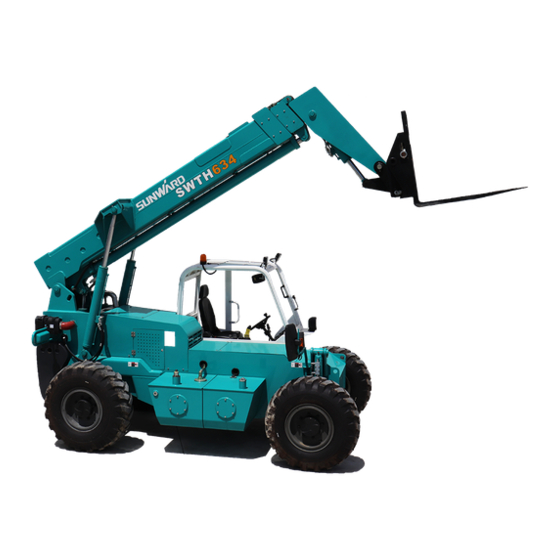
- Page 1 Operation & Maintenance Manual TELESCOPIC HANDLER SUNWARD INTELLIGENT EQUIPMENT CO., LTD.
-
Page 2: Preface
By complying with these instructions, the truck driver will be able to get the best performances from his vehicle. The terms “right” and “left”, “front” and “rear” used in this manual refer to positions viewed by the driver seated normally in the driving seat. SUNWARD... -
Page 3: Table Of Contents
TABLE OF CONTENTS PREFACE ............................0 TABLE OF CONTENTS ........................1 SAFETY INSTRUCTIONS ......................3 ORIGINAL REPLACEMENT PARTS AND ATTACHMENTS .............. 3 DRIVER’S OPERATING INSTRUCTION................... 3 ENVIRONMENT.......................... 5 AUTHORIZATION TO OPERATE ....................5 OPERATING INSTRUCTIONS ..................... 5 STOPPING THE TELESCOPIC HANDLER ..................6 DESCRIPTION ........................ - Page 4 MAINTENANCE ........................28 FILTERING ELEMENTS AND BELTS ..................28 LUBRICANT ..........................28 SERVICING SCHEDULE CONTENT .................... 29 SERVICING SCHEDULE DESCRIPTION ..................31 EVERY DAY OR EVERY 10 HOURS SERVICE ..............31 5.4.1 EVERY 50 HOURS SERVICE ................... 32 5.4.2 EVERY 250 HOURS SERVICE ..................34 5.4.3 EVERY 500 HOURS SERVICE ..................
-
Page 5: Safety Instructions
Only the manufacturer knows the details of the lift truck design and therefore has the best technological capability to carry out maintenance. Original replacement parts are distributed exclusively by SUNWARD and its dealer network. DRIVER’S OPERATING INSTRUCTION. Caution Whenever you see this symbol it means :“Warning! Be careful! Your safety or the safety of the lift truck is at risk. - Page 6 equipment. Always be aware of his stopping distance. On the basis of experience, there are a number of possible situations in which operating the lift truck is contra-indicated. Such foreseeable abnormal uses, the main ones being listed below, are strictly forbidden. ...
-
Page 7: Environment
ENVIRONMENT. A lift truck operating in an area without fire extinguishing equipment must be equipped with an individual extinguisher. There are optional solutions, consult your agent or dealer. Take into account climatic and atmospheric conditions of the site of utilisation. For operation under average climatic conditions, i.e.: between -15 °C and + 35 °C, correct levels of lubricants in all the circuits are checked in production. -
Page 8: Stopping The Telescopic Handler
13) Ensure that the service brakes and the sound alarm are working properly. 14) Drive according to, and at an appropriate speed for, the conditions and state of the terrain. 15) Slow down before executing a turn. 16) In all circumstances make sure you are in control of your speed. 17) On damp, slippery or uneven terrain, drive slowly. -
Page 9: Description
DESCRIPTION 1.Telescopic boom 2.Dynamical system 3.Hydraulic cylinder 4.Cab 5.Travelling system 6.Quick-change system 7.Attachment tool 8.Covering parts 9.Fuel tank 10.Hydraulic fluid tank 11.Chassis... -
Page 10: Instrument Panel
INSTRUMENT PANEL Fuel gage Indicates the quantity of diesel available in the tank Engine cooling water-thermometer dash unit If the temperature reaches 103°C, the warning light turns on, immediately turn off the engine and troubleshoot the cause in the cooling circuit. Load indicator The indicator shows the machine load torque, when then load torque is bigger than the set value, the pointer will point to the red zone,... - Page 11 Neutral position indicating light Light on, the machine is in the neutral position. Travel brake system pressure Steering mode indicator light Steering mode indicator light Steering mode indicator light Warning light for parking brake When illuminated indicates that the parking brake is applied. Engine preheat indicating light This warning light comes on when the engine is preheated.
- Page 12 Air filter blocked indicator light This warning light comes on when the ignition is switched on and should go out when the engine is running. If the warning light should come on when the engine is running stop the engine immediately, and check the alternator belt and electrical circuit.
-
Page 13: Accelerator Pedal(Pic. B
ACCELERATOR PEDAL(PIC. B) This pedal is used to vary the truck speed by modifying the engine rpm rate. FOOT BRAKE(PIC. A) The foot brake control the brake that acts on the front and rear wheels, thus slowing and stopping the lift truck. STEERING WHEEL Turning the stering wheel to control the direction of the machine.There are three different steering module to choose. -
Page 14: Rocker Switch Consle
ROCKER SWITCH CONSLE Steering mode switch Press this switch to choose three different sterring modes. Attachment tool switch Press this switch to control the attachment tool switch. Signal switch Press this switch to choose steering indicating light Work light switch Press this switch to control front high beam frontlow beam. -
Page 15: Combination Control Switch
COMBINATION CONTROL SWITCH COMBINATION CONTROL SWITCH 1.Gear select switch There are three speed gear on this switch,turn the switch from 1 to 3 to adjust three differenet speed. 2.Reversing contol switch F=Forward gear ……………… push the knob forward(machine move forward) N=Neutral gear ………………... -
Page 16: Electro-Hydraulic Proportional Servocontrols
2.10 ELECTRO-HYDRAULIC PROPORTIONAL SERVOCONTROLS PIC.(A) PIC.(B) The servo control knob(PIC. A) can carry on 3 actions: lifting, tipping fork and extend/retract boom at the same time. To lift load, pull the lever back To lower load, push the lever forward To tip the fork forward, push the lever left To crowd the forks back, push the lever to the right. -
Page 17: Seat
2.11 SEAT 1. Headrest adjustment Adjust the headrest to a suitable place 2. Armrest adjustment Adjust the armrest to a suitable place 3. Beckrest adjustment Adjust the beckrest to a suitable place 4. Levelling adjustment Adjust the seat to a suitable place. 2.12 SAFETY BELT Before starting the engine,adjust the seat as necessary,and then adjust the safety belt as... -
Page 18: Rearview Mirror
2.13 REARVIEW MIRROR here are three rearview mirrors on the machin,two on the each side of the cab,the last one is on the right front of the machine. Attention: Before start the machine,make sure you have the best vision. -
Page 19: Machine Operation
MACHINE OPERATION AUTHORIZED OPERATION Wear clothes suited for driving the lift truck, avoid loose clothes. Never operate the vehicle when hands or feet are wet or soiled with greasy substances. For increased comfort, adjust the driver’s seat to your requirements and adopt the correct position in the driver’s cab。... -
Page 20: Start The Engine
START THE ENGINE Into the cab,adjust the seat. Adjust the rearview mirrors to get the best vesion. Fasten the belt. Make ssre the reversing contol switch is on the neutral gear. Turn the key to start the engine. Important!Do not start the engine twice in 30s. After start the engine,make the engine run in the low speed about 30~60s . -
Page 21: Drive
3.5 DRIVE Fasten the belt,start the engine,push the foot brake and then lossen the hand brake. Choose the suitable gear.。 Adjust the reversing contol switch. Lossen the foot brake and push the accelerator pedal. 3.6 STEER Push the foot brake to slow down the machine. ... - Page 22 his steering will provide a smallturning radius,the rear-wheel will follow the path of the front-wheel, it also provide advantagesin the mud and sand pavement. 2. Front-wheel steer This mode can be used in many different kings of driving conditions. Crab row to steer Warning:...
-
Page 23: Mount The Accessory With Manual Lock
MOUNT THE ACCESSORY WITH MANUAL LOCK A Engaging the accessory Check that the accessory is in a position which simplifies connection of the snap coupling. If it is improperly positioned, take the necessary precautions and adapt it to the conditions of maximum safety. -
Page 25: Load Handling
LOAD HANDLING 3.10 1. Weight of load and center of gravity Carrying a load greater than the rated capacity for the lift truck or for the attachment is prohibited. Before taking up a load, you must know its weight and its center of gravity. The load chart relating to your lift truck is valid for a weight with its center of gravity 500 mm from the heel of the forks For a load with a higher center of gravity, consult your agent or dealer. - Page 26 3. Taking up a high load on tyres Under no circumstances should you pick up a load if the lift truck is not in a horizontal position. (See paragraph: G -HORIZONTAL POSITION OF THE LIFT TRUCK in the chapter: LOAD HANDLING).
- Page 27 4. Laying a high load on tyres Under no circumstances should you lay down a load if the lift truck is not a horizontal position. (See paragraph: G - HORIZONTAL POSITION OF THE LIFT TRUCK in the chapter: LOAD HANDLING). Approach the load in the transport position in front of the pile.
-
Page 28: Transport And Store
TRANSPORT AND STORE SLING THE LIFT TRUCK Take into account the position of the lift truck gravity center for lifting TRANSPORT THE LIFT TRUCK ON A PLATFORM Ensure that the safety instructions connected to the platform are respected before the loading of the lift truck and that the driver of the means of transport is informed about the dimensions and the weight of the lift truck (See chapter: CHARACTERISTICS in paragraph: 2 - DESCRIPTION). -
Page 29: Storage
STORAGE 4.3.1 Long-term storage When you want to store the machine for a long time, please put the piston rod into the cylinder to protect the wear of the rod.and please clean the covers of the machine. 4.3.2 Before storage ... -
Page 30: Maintenance
MAINTENANCE 5.1 FILTERING ELEMENTS AND BELTS 250 H,repalce Engine oil filter Every Air filter cartridges 500 H, clean Every Transmission oil filter Every 500 H,repleace Hydraulic oil filter Every 500 H,repleace cartridge Engine belt 1000 Every H,cheak Hydraulic oil tank Every H,cheak vent... -
Page 31: Servicing Schedule Content
5.3 SERVICING SCHEDULE CONTENT A – EVERY DAY OR EVERY 10 HOURS SERVICE A1-- Engine oil level. A2-- Check the cooling fluid level. A3-- Check the fuel prefilter. A4-- Cheak the level of the hydraulic driver oil B -- EVERY 50 HOURS SERVICE B1-- Clean the air filter. - Page 32 G3 -- Check the plate profile for wear G4 -- Check wear on the side of the chain H -- OCCASIONAL MAINTENANCE H1:Engine maintenance H2: Change a wheel Periodically check to make sure that the anti-tipping safety system operates correctly whenever maintenance work is carried out.
-
Page 33: Servicing Schedule Description
5.4 SERVICING SCHEDULE DESCRIPTION 5.4.1 EVERY DAY OR EVERY 10 HOURS SERVICE Engine oil level Before checking the oil level, make sure that the engine is off and that the truck is on a flat surface. To obtain an accurate indication, wait a few minutes after the engine has been switched off to allow the oil to flow into the crankcase. -
Page 34: Every 50 Hours Service
Check that there are no leaks A3: Check the fuel prefilter. Cheak the fuel oil level. Stop the engine.turn the port at the bottom of the filter counterclockwise,exhaust the water from the filter until the fuel flow out. - Page 35 B3: Check the tyre pressure and wheel nut torque. Check and adjust the tyre pressure Check the condition of the tyres. There should be no cuts, signs of wear, etc. Check that the wheel nuts are correctly torqued Attention:...
-
Page 36: Every 250 Hours Service
5.4.3 EVERY 250 HOURS SERVICE Alternator belt tension The tension of the alternator fan belt must be adjusted, by exercising a normal pressure with the thumb, the belt flexure is about 0.394 in. If the tension is wrong, slacken screws 1 and 2 by 2 or 3 turns and turn the alternator unit so that the belt tension is correct. - Page 37 C5:Grease the pivot pin of telescopic boom. C6:Grease the pivot pin of quick coupling. C7:Grease the pins of fork tilting cylinder foot and rod. C8:Grease the pins of lifting cylinder foot and rod. C9:Grease the pins of front and rear axle. C10:Grease the pins of front and rear axle soleplate C11:Grease the pins of the cardan jiont.
- Page 38 C14:Cheak the chains tension Inspect the leaf chains for wear. Run the boom outslowly to inspect. Conditions to look for include:cracked or broken plates, protruding or turned pins,and excessive wear. With a steel tape, measure 16 links。of the strand that flexes over the sheaves. If the section measures 10.3in. or more, the chain should be replaced.
-
Page 39: Every 500 Hours Service
5.4.4 EVERY 500 HOURS SERVICE D1: Replace the air filter cartridge The air used to burn the fuel is purified by a dry air filter. The lift truck should never ever be used if the air filter has been removed or is damaged. - Page 40 D3: Replace the secondary fuel filter Thoroughly clean fuel filter assembly and surrounding area. Using a filter wrench, remove the filter from the filter head. Inspect filter head for cleanliness. Clean as required. Apply a small amount of fuel to the sealing gasket of the replacement filter.
-
Page 41: Every 1000 Hours Service
5.4.5 EVERY 1000 HOURS SERVICE E1: Replace the hydraulic oil Before proceeding with these operations, check that the truck is standing on a perfectly horizontal surface and that the engine is off. Place a receptacle under drain plug. ... -
Page 42: Every 2000 Hours Service
E4: Change the oil in the front axle reduction gear Set the truck on a horizontal surface with the engine off and the oil in the reduction gear still hot. Place a receptacle under drain plug. Remove plug 1 and allow the oil to drain out. Remove fill and level plug to ensure that all oil has drained out. -
Page 43: Occasional Maintenance
5.4.8 OCCASIONAL MAINTENANCE H1:Engine maintenance Plesea read the operation manual of Deutz H2: Change a wheel In the event of a wheel being changed on the public highway, make sure of the following points : Stop the lift truck, if possible on even and hard ground. ... -
Page 44: Description
DESCRIPTION 6.1 SPECIFICATION 6.1.1 Engine Manufacturer…………………………Deutz Rated power……………………………55.4kW Series……………………………TCD3.6 L4 HT Rated speed……………………………2300rpm 6.1.2 Chassis Transmission………………………………Hydrodynamic drive Max.diving speed…………………………18 mph Steering mode………………………………4-wheel/2-wheel/ Crab row Hydraulic built-in wet disc brak……4-wheel Bridge………………………………………Dana 6.1.3 Type Series………………………………16/70-20 6.1.4 Hydraulic circuit Pump………………………………gear pump The max flow………………………110 l/min Preesure………………………………207 bar Hydraulic oil tank………………………29 gal... -
Page 45: Specifications
6.2 SPECIFICATIONS 6.2.1 Performance Rated load…………………………………6000 lbs Max.height…………………………………34.5 ft. Rated load at the max.height…………4001 lbs Max. forward distance……………………22.97 ft. 6.2.2 Parameter Total weight……………………………………16534.7 lbs Total length……………………………………16.08 ft. Total width………………………………………7.61 ft. Ground clearance………………………………13.78 in. Wheel base………………………………………9.19 ft. Turn radius………………………………………12.47 ft. Total height………………………………………7.87 ft. Frame leveling……………………………………±10°... -
Page 46: Dimension And Load Charts
6.3 DIMENSION AND LOAD CHARTS 6.3.1 DIMENSION A Height……………………………………………………………………… 7.87 ft. … B Width 7.61 ft. …………………………………………………………………………………… C Track 6.33 ft. …………………………………………………………………………………… D Length 19.59 ft. ………………………………………………………………………………… E Length at fork-holder plate 16.08 ft. ………………………………………………… F Wheelbase 9.19 ft. ………………………………………………………………………………... -
Page 47: Load Charts
6.3.2 LOAD CHARTS The load capacity diagrams are only valid with the safety system properly activated... -
Page 48: Attachment Tool
ATTACHMENT TOOL ATTENTIONS Follow the data provided in the load diagram. Never attempt to raise loads greater than those permitted in the load charts supplied with the machine. Transport the load in low position with the telescopic boom fully retracted. ... -
Page 49: Attachment Tool
7.2 ATTACHMENT TOOL This manchine can use many kinds of attachment tool to adpat to different working environment. Sunward can design the attachment tool to meet the customers. 7.2.1 Floating goods fork Feature... -
Page 50: Light Bucket
7.2.2 Light bucket Feature Dimension(ft.) Rated dipper Weight Name Serial namber capacity(gar) (lbs.) Length Width Height Light 815314000000 206.8 2.89 7.55 2.64 bucket 7.2.3 Clip with bucket Feature Dimension(ft.) Rated dipper Weight Name Serial namber Max. capacity(gar) (lbs.) Length Width Height distance Clip... -
Page 51: Clipping Fork
7.2.4 Clipping fork Feature Dimension(ft.) Rated Weight Name Serial namber load Max. (lbs.) Length Width Height (lbs.) distance Clipping 815325000000 4409 4.23 3.69 4.27 fork 7.2.5 Dozer blade Feature Dimension(ft.) Deflection Weight Name Serial namber angle (lbs.) Length Width Height Dozer 815321000000 3.02... -
Page 52: Hay Fork
7.2.6 Hay fork Feature Rated Dimension(ft.) Weight Name Serial namber load (lbs.) Length Width Height (lbs.) Hay fork 815323000000 4.56 3.61 2205 7.2.7 Simple sling Feature Rated Dimension(ft.) Weight Name Serial namber load (lbs.) Length Width Height (lbs.) Simple 815320000001 2.35 2.56 7716... -
Page 53: Appendix
APPENDIX ELECTRICAL SCHEMATIC DIAGRAM... -
Page 54: Hydraulic System Diagram
HYDRAULIC SYSTEM DIAGRAM... -
Page 55: Manufacturer Data
MANUFACTURER DATA Company: SUNWARD ` Trade mark: Add: Sunward Intelligent Industrial Park Ⅲ ,Dongba Road,Xingsha,Changsha,Hunan, China. Tel: 0086-0731-83572372 Maintenance point: our office in various area Distributor information: Distributor information: Distributor Add: Tel: Fax: Email: Contact: Remark:...
Need help?
Do you have a question about the SWTH634 and is the answer not in the manual?
Questions and answers