Table of Contents
Advertisement
Quick Links
This manual details the
procedure for fl ush mounting
SolarMount to a pitched roof.
If your installation includes tilt
legs, see also the instructions
shipped with the leg kit.
Contents
Installer reponsibility . . . . . . 2
installation area . . . . . . . . . . . 2
Laying out L-feet . . . . . . . . . . 3
Installing L-feet . . . . . . . . . . . 3
Laying out standoffs . . . . . . . 4
Installing standoffs . . . . . . . . 4
rails . . . . . . . . . . . . . . . . . . . . . 5
Installing the modules . . . . . 6
Part quantities
®
SolarMount
Rail Sets
No. of
Rail length (inches)
rails
48 - 106
2
120 - 180
2
192 - 216
2
226 - 288 (w/ splice)
2
300 - 336 (w/ splice)
2
348 - 408 (w/ splice)
2
420 - 432 (w/ splice)
2
Top Mounting Clamp Sets, Sizes A - F, G*, H†, and J
Modules
End
Mid
per row
clamps
clamps
2
4
2
3
4
4
4
4
6
5
4
8
6
4
10
7
4
12
8
4
14
9
4
16
10
4
18
11
4
20
12
4
22
* In size G, end clamps and mid clamps are identical, except that end clamps
include spacers. For illustration, see page 14.
† In size H, end clamps and mid clamps are identical. Hexhead bolts replace
T-bolts. For illustration, see page 14.
UniRac welcomes input concerning the accuracy and user friendliness of
this publication. Please write to publications@unirac.com.
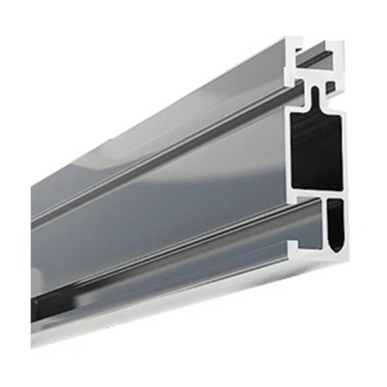
T-bolt slot
for module
mounting
Footing
bolt slot
3
⁄
˝ footing
3
⁄
˝ fl ange
8
8
L-feet
bolts
nuts
4
4
6
6
8
8
10
10
10
12
12
12
14
14
14
16
16
16
¼˝ module
¼˝x
5
⁄
˝
¼˝ fl ange
8
T-bolts
safety bolts
6
2
8
2
10
2
12
2
14
2
16
2
18
2
20
2
22
2
24
2
26
2
Installation with Top Mounting Clamps
Installation Manual 201.1
U.S. Des. Patent No. D496,248S. Other patents pending.
4
6
8
Figure 3. Exploded view of a low-profi le installation
mounted fl ush to the roof with L-feet.
Wrenches and torque
nuts
8
10
12
¼˝ hardware
14
3
⁄
˝ hardware
8
16
18
20
22
24
26
28
Pub 050304-1ii
March 2005
Mid
clamp
L-foot
Wrench
Recommended
size
torque (ft-lbs)
7
⁄
˝
15
16
9
⁄
˝
30
16
Stainless steel hardware can seize up, a
process called galling. To sig nifi cant ly re-
duce its like li hood, (1) apply lubricant to
bolts, preferably an anti-seize lu bri cant, available
at auto parts stores, (2) shade hardware prior to
installation, and (3) avoid spinning on nuts at high
speed. See Installation Supplement 910, Galling
and Its Prevention, at www.unirac.com.
© 2005 by UniRac, Inc.
All rights reserved.
End
clamp
Advertisement
Table of Contents

Subscribe to Our Youtube Channel
Related Manuals for UNIRAC SolarMount


Summary of Contents for UNIRAC SolarMount
- Page 1 † In size H, end clamps and mid clamps are identical. Hexhead bolts replace T-bolts. For illustration, see page 14. Pub 050304-1ii UniRac welcomes input concerning the accuracy and user friendliness of © 2005 by UniRac, Inc. this publication. Please write to publications@unirac.com.
- Page 2 Installer responsibility • Using only UniRac parts and installer-supplied The installer is solely responsible for: parts as specifi ed by UniRac (substitution of parts may void the warranty); • Complying with all applicable local or national building codes, including any that may supercede •...
- Page 3 Drill pilot holes through the roof into the center of the rafter at each L-foot lag bolt hole location. Consult procedural step 6 and Table 4 (p. 8) in SolarMount Code Compliant Planning and Assembly to select the lag bolts that meet building code wind load requirements.
- Page 4 Download the version for the applicable building code at www.unirac.com. Remove the tile or shake underneath each standoff location, exposing Figure 8. SolarMount standoff choices: alumi- the roofi ng underlayment. Ensure that the standoff base lies fl at on num 2-piece (left), steel fl at-top (center), and the underlayment, but remove no more material than required for the steel raised fl...
- Page 5 Foreign matter will cause bolts to bind as they slide in the slots. Installing Splices. If your installation uses SolarMount splice bars, attach the rails together (Fig. 11) before mounting the rails to the foot- ings. Use splice bars only with fl ush installations or those that use low-profi...
- Page 6 (cross section) (cross section) SolarMount rail with Size H clamps SolarMount rail with G clamps and spacer ules with low lips) are identical and employ hexhead Figure 18. Size G clamps (for modules with high lips) bolts in place of T-bolts; their heads slide into Solar-...
Need help?
Do you have a question about the SolarMount and is the answer not in the manual?
Questions and answers