Table of Contents
Advertisement
Quick Links
Advertisement
Table of Contents

Subscribe to Our Youtube Channel
Related Manuals for UNIRAC SOLARMOUNT ASCENDER 2-ROW ELEVATED


Summary of Contents for UNIRAC SOLARMOUNT ASCENDER 2-ROW ELEVATED
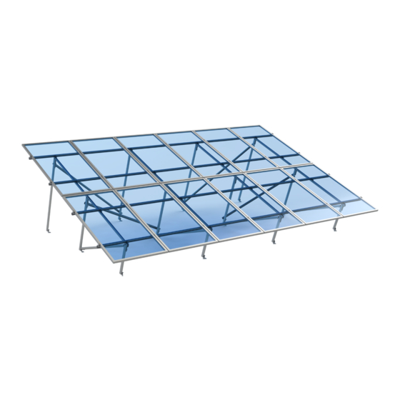
- Page 1 INSTALLATION GUIDE SOLARMOUNT ASCENDER 2-ROW ELEVATED UNIRAC Code-Compliant Installation Manual © 2022 by Unirac, Inc. All rights reserved. PUB2023APR23 UNIRAC welcomes input concerning the accuracy and user-friendliness of this publication. Please write to publications@unirac.com.
-
Page 2: Table Of Contents
INSTALLATION GUIDE SOLARMOUNT ASCENDER 2-ROW ELEVATED TABLE OF CONTENTS SYSTEM COMPONENTS ........1-3 SYSTEM LAYOUT . - Page 3 SYSTEM COMPONENTS SOLARMOUNT ASCENDER 2-ROW ELEVATED INSTALLATION GUIDE PAGE ASCENDER RAIL (A1R181M) Functions as . Aluminum extrusion, available in mill finish. FRONT TILT LEG - Supports NS rail. Use one Front Tilt leg per frame/bay. MID TILT LEG - Supports NS rail. Use one Mid Tilt leg per frame/bay.
-
Page 4: System Components
SYSTEM COMPONENTS SOLARMOUNT ASCENDER 2-ROW ELEVATED INSTALLATION GUIDE PAGE ASCENDER TILT PLATE ASSEMBLY (A1TP001) Connects Tilt legs with NS rail and NS bracing with Tilt legs. T-BOLT AND SERRATED FLANGE NUT (3/8” X 1.2” SS) (009022S) Use at Tilt plate assembly, EW brace to L-foot and Tilt leg to L-foot connection. - Page 5 SYSTEM COMPONENTS SOLARMOUNT ASCENDER 2-ROW ELEVATED INSTALLATION GUIDE PAGE IMAGE 1-SYSTEM COMPONENTS SCALE 1 / 2.25 ASCENDER BEAM CLIP ASSEMBLY (A1BC102) S.no. Required Tools Pre-assembled beam clip assembly contains beam clip, Torque Wrench beam plate, stud, keps nut, spring. Connects the EW beam to the NS rail.
-
Page 6: System Layout
SYSTEM LAYOUT SOLARMOUNT ASCENDER 2-ROW ELEVATED INSTALLATION GUIDE PAGE PLANNING YOUR ASCENDER INSTALLATIONS LAYING OUT L-FEET FOR TOP CLAMPS Center the installation area over the structural members as much as possible. Refer to the Ascender Design tool for details of EW span and NS Spacing. Mark the Leave enough room to safely move around the array during installation. -
Page 7: Thermal Break
THERMAL BREAK SOLARMOUNT ASCENDER 2-ROW ELEVATED INSTALLATION GUIDE PAGE EXPANSION JOINT USED AS THERMAL BREAK Expansion joints prevent buckling of rails or system connections failure due to thermal expansion. Determine location of expansion joints prior to installation of roof attachments and rails. To create a thermal expansion joint, set gap between rails that is sufficient for proper installation of end clamps and tooling to achieve the required torque. -
Page 8: System Setup Distances
SYSTEM SETUP-DISTANCES SOLARMOUNT ASCENDER 2-ROW ELEVATED INSTALLATION GUIDE PAGE Tilt Angle (Range) Roof Clearance Range (cm) 10° to 20° 25.4 to 50.8 TILT ANGLE ( θ )° TILT ANGLE (90- θ )° ROOF CLEARANCE NS SPACING NS SPACING • Install front tilt plate at 6.35cm from edge of NS rail and rear tilt plate at 8.89cm from edge of NS rail. Install mid tilt plate at center of front and rear tilt IMAGE 1- DISTANCES SCALE 1 / 9 plate. -
Page 9: System Installation Steps
SYSTEM INSTALLATION STEPS SOLARMOUNT ASCENDER IMAGE 2-STEP B. ROTATE THE T-BOLT SCALE 3 : 1 2-ROW ELEVATED INSTALLATION GUIDE PAGE COMMON STEPS FOR ALL T-BOLT INSTALLATIONS: STEP A. INSERT T-BOLT Insert T- Bolt into the rail and position the T-Bolt. STEP B. - Page 10 SYSTEM INSTALLATION STEPS SOLARMOUNT ASCENDER 2-ROW ELEVATED INSTALLATION GUIDE PAGE STEP 1. CUT RAIL INTO SECTIONS: Cut rails into needed lengths and verify the count of each part. Refer to the Ascender Design tool to find the length and quantities of the following parts: XXX cm 1 : Tilt Post - Front XX c/u...
- Page 11 IMAGE 2-STEP B. ROTATE THE T-BOLT SCALE 3 : 1 SYSTEM INSTALLATION STEPS 1-STEPA. INSERT T BOLT SOLARMOUNT ASCENDER IMAGE 2-STEP B. ROTATE THE T-BOLT SCALE 2.5: 1 SCALE 3 : 1 IMAGE 1-STEPA. INSERT T BOLT SCALE 2.5: 1 IMAGE 3-SLIDE TILT PLATE INTO THE NS RAIL SCALE 1.25 : 1 2-ROW ELEVATED...
- Page 12 SYSTEM INSTALLATION STEPS SOLARMOUNT ASCENDER 2-ROW ELEVATED IMAGE 2-STEP B. ROTATE THE T-BOLT IMAGE 2-STEP B. ROTATE THE T-BOLT IMAGE 5-ALL TILT LEGS TO NS RAIL IMAGE 5-ALL TILT LEGS TO NS RAIL SCALE 3 : 1 SCALE 3 : 1 1-STEPA.
- Page 13 IMAGE 7-NS BRACE FACE EPRESENTATION SCALE 1.5 : 1 IMAGE 1-TILT PLATE TO NS RAIL SCALE 2 : 1 SYSTEM INSTALLATION STEPS SOLARMOUNT ASCENDER IMAGE 7-NS BRACE FACE EPRESENTATION SCALE 1.5 : 1 IMAGE 1-TILT PLATE TO NS RAIL 2-ROW ELEVATED SCALE 2 : 1 INSTALLATION GUIDE PAGE...
- Page 14 SYSTEM INSTALLATION STEPS SOLARMOUNT ASCENDER 2-ROW ELEVATED INSTALLATION GUIDE PAGE STEP 6. ARRAY LAYOUT Refer to the calculator tool for details of EW span and NS Spacing. Mark the location for the L-feet. Span/ Bay: EW distance between two frames. Refer to figure B for frame. EW SPACING EW SPACING EW SPACING...
- Page 15 SYSTEM INSTALLATION STEPS SOLARMOUNT ASCENDER 2-ROW ELEVATED INSTALLATION GUIDE PAGE STEP 8. ATTACH L-FEET TO ANCHORS Using a 3/8” bolt or all-thread with nut, install L-Feet and secure to concrete anchors. Ensure all L-Feet are oriented in the same direction. Follow anchor manufacturer requirements for torque specification.
- Page 16 SYSTEM INSTALLATION STEPS SOLARMOUNT ASCENDER IMAGE 6-FULL FRAME SCALE 1 / 7 IMAGE 4-ONE T-BOLT EDGE DISTANCE SCALE 2 : 1 IMAGE 5-TWO T-BOLT DISTANCE 2-ROW ELEVATED SCALE 2 : 1 INSTALLATION GUIDE PAGE STEP10. INSTALL ALL THE FRAMES Install the rest of the frames at specified locations in step 6 by repeating step 9. IMAGE 8-BOTTOM L-FEET REAR TILT LEG IMAGE 6-TOP L-FEET FOR EW BRACE SCALE 1.5: 1...
- Page 17 SYSTEM INSTALLATION STEPS SOLARMOUNT ASCENDER 2-ROW ELEVATED INSTALLATION GUIDE PAGE EW BRACE IMAGE 8-BOTTOM L-FEET REAR TILT LEG IMAGE 7-BOTTOM L-FEET MID TILT LEG SCALE 1.5: 1 SCALE 1.5: 1 IMAGE 6-TOP L-FEET FOR EW BRACE IMAGE 1-SLIDE BEAM CLIP INTO NS RAIL SCALE 1 : 1 SCALE 0.8 : 1 IMAGE 8-BOTTOM L-FEET REAR TILT LEG...
- Page 18 SYSTEM INSTALLATION STEPS SOLARMOUNT ASCENDER 2-ROW ELEVATED INSTALLATION GUIDE PAGE STEP 14. SECURE L-FOOT ON TILT LEGS FOR EW BRACE L-Foot will only be installed on Mid and Rear tilt leg for the EW Brace connection. To connect the high side L-Foot, loosen the 2nd nut on the Tilt plate and place the L-Foot as shown in the Figure H.
- Page 19 IMAGE 4-CANTILIVER LIMIT SCALE 1 / 13 SYSTEM INSTALLATION STEPS SOLARMOUNT ASCENDER 2-ROW ELEVATED IMAGE 1-SECURE L-FOOT TO EW BRACE INSTALLATION GUIDE PAGE SCALE 2 : 1 IMAGE 1-SECURE L-FOOT TO EW BRACE SCALE 2 : 1 Figure K GE 2-EQUAL SPAN DISTRIBUTION Figure M SCALE 1 / 12 IMAGE 2-EQUAL SPAN DISTRIBUTION...
- Page 20 SYSTEM INSTALLATION STEPS SOLARMOUNT ASCENDER 2-ROW ELEVATED INSTALLATION GUIDE PAGE STEP 18. INSTALL PV MODULES Using supplied clamps, attach modules to EW beams. Install end-clamp first then continue to use mid-clamps along the array until the final module, then use an end-clamp. Notes: 1.
- Page 21 SYSTEM INSTALLATION STEPS SOLARMOUNT ASCENDER 2-ROW ELEVATED INSTALLATION GUIDE PAGE ENDCLAMP 1.91 cm 3/4" MIN 1. Position clamp to align T-bolt 2. Rotate clamp clockwise until 3. Place module at least 1.91 cm 4. While applying pressure to with rail slot. Lower clamp and the T-bolt fully engages to the from end of rail and position clamp hold the clamp against the...
- Page 22 SYSTEM INSTALLATION STEPS SOLARMOUNT ASCENDER 2-ROW ELEVATED INSTALLATION GUIDE PAGE MIDCLAMP MID CLAMP INSTALLATION 1. Position clamp to align T-bolt with 2. Rotate clamp clockwise 63° of a Mid clamp is supplied as an assembly with a T-bolt. Clamp rail slot. Lower clamp and insert turn to fully engage T-bolt inside rail assemblies can be positioned in rail prior to module placement.
- Page 23 SYSTEM INSTALLATION STEPS SOLARMOUNT ASCENDER 2-ROW ELEVATED INSTALLATION GUIDE PAGE PRO SERIES ENDCLAMP INSTALL MODULE END CLAMPS: The End INSTALL END CLAMPS ON RAIL: POSITION END CLAMPS: NOTE: To assist insertion of clamp into clamp is supplied as an assembly with a 1/2" Slide end clamp on to rail by Slide end clamp assembly rail slot, Pressure may be applied to...
- Page 24 SYSTEM INSTALLATION STEPS SOLARMOUNT ASCENDER 2-ROW ELEVATED INSTALLATION GUIDE PAGE STEP 19. FINAL CHECK Check all fasteners to verify correct torque values and proper T-bolt engagement with rail. IMAGE 2-FINAL CHECK SCALE 1 / 15...
-
Page 25: Microinverter Mounting
MICROINVERTER MOUNTING SOLARMOUNT ASCENDER IMAGE 1-INSTALL MICROINVERTER MOUNT T-BOLT SCALE 1 / 1.5 2-ROW ELEVATED INSTALLATION GUIDE PAGE IMAGE 2-INSTALL MICROINVERTER T T-BOLT SCALE 1 / 1.5 IMAGE 2-INSTALL MICROINVERTER SCALE 1 / 1.5 IMAGE 1-INSTALL MICROINVERTER MOUNT T-BOLT IMAGE 2-INSTALL MICROINVERTER SCALE 1 / 1.5 SCALE 1 / 1.5 INSTALL MICROINVERTER MOUNT T-BOLT:... -
Page 26: Standard System Grounding
10-14 AWG: 20 in-lbs IlSCO Lug #10-32 7/32" ILSCO LAY-IN LUG CONDUCTOR - UNIRAC P/N 008009P: Alternate Grounding Lug- Drill, deburr hole and bolt thru both rail walls per table. •Torque value depends on conductor size. TORQUE VALUE 5 ft lbs. -
Page 27: Bonding Connections And Grounding Paths
SOLARMOUNT ASCENDER Bonding Connections & Grounding Paths 2-ROW ELEVATED INSTALLATION GUIDE PAGE BONDING MID CLAMP ASSEMBLY BONDING RAIL SPICE BAR Aluminum mid clamp with stainless steel bonding pins that pierce module 5/16" self drilling screw creates bond between splice bar and EW beams. frame anodization to bond module to module through clamp. - Page 28 SOLARMOUNT ASCENDER Bonding Connections & Grounding Paths 2-ROW ELEVATED INSTALLATION GUIDE PAGE HEX NUT W/ CAPTIVE LOCK WASHER BONDING T-BOLT WEEBLUG (OR ILSCO LUG) BONDING MICROINVERTER MOUNT RACK SYSTEM GROUND Hex nut with captive lock washer bonds metal WEEB washer dimples pierce rail to create bond microinverter flange to stainless steel T-bolt.
- Page 29 SOLARMOUNT ASCENDER Bonding Connections & Grounding Paths 2-ROW ELEVATED INSTALLATION GUIDE PAGE E-W BEAM Fault Current Ground Path Module Grounding Rail Grounding BONDING UAF MID Clamp Min. 10 AWG, 105°C Copper Wire Bonding UAF End Clamp E-W BEAM...
- Page 30 SOLARMOUNT ASCENDER Bonding Connections & Grounding Paths 2-ROW ELEVATED INSTALLATION GUIDE PAGE NS BRACE FLAT ROOF Fault Current Ground Path Bonding Connection Min. 10 AWG, 105°C Copper Wire Rail Grounding...
-
Page 31: Code Compliance Notes
This racking system may be used to ground and/or mount a PV module complying with UL1703 or UL61730 only when the specific module has been evaluated for grounding and/or mounting in compliance with the included instructions. UL2703 CERTIFICATION MARKING Unirac SM Ascender is listed to UL 2703. Certification marking is embossed on all mid clamps and Universal AF end clamps as shown. -
Page 32: Mechanical Load Test
SM Ascender load rating. Please consult the PV module manufacturer's installation guide for more information. In addition to UL 2703 certification, Unirac performs internal testing beyond the requirements of certification tests in order to establish system functional limits, allowable loads, and factors of safety. -
Page 33: Compatible Modules
COMPATIBLE MODULES SOLARMOUNT ASCENDER 2-ROW ELEVATED SYSTEM CERTIFICATION PAGE Electrical Bonding and Grounding Test Modules The list below is not exhaustive of compliant modules but shows those that have been evaluated and found to be electrically compatible with the SM ASCENDER system. Manufacture Module Model / Series Manufacture... - Page 34 COMPATIBLE MODULES SOLARMOUNT ASCENDER 2-ROW ELEVATED SYSTEM CERTIFICATION PAGE Electrical Bonding and Grounding Test Modules The list below is not exhaustive of compliant modules but shows those that have been evaluated and found to be electrically compatible with the SM ASCENDER system. Manufacture Module Model / Series Manufacture...
- Page 35 COMPATIBLE MODULES SOLARMOUNT ASCENDER 2-ROW ELEVATED SYSTEM CERTIFICATION PAGE Electrical Bonding and Grounding Test Modules The list below is not exhaustive of compliant modules but shows those that have been evaluated and found to be electrically compatible with the SM ASCENDER system. Manufacture Module Model / Series Manufacture...
- Page 36 COMPATIBLE MODULES SOLARMOUNT ASCENDER 2-ROW ELEVATED SYSTEM CERTIFICATION PAGE Electrical Bonding and Grounding Test Modules The list below is not exhaustive of compliant modules but shows those that have been evaluated and found to be electrically compatible with the SM ASCENDER system. Manufacture Module Model / Series Yingli...
Need help?
Do you have a question about the SOLARMOUNT ASCENDER 2-ROW ELEVATED and is the answer not in the manual?
Questions and answers