Table of Contents
Advertisement
CANADIAN
HEAD OFFICE
AND FACTORY
1401 HASTINGS CRES.
SE
CALGARY, ALBERTA
T2G 4C8
Ph: (403) 287-4774
Fx: 888-364-2727
SALES OFFICES ACROSS CANADA AND USA
Retain instructions with unit and maintain in a legible condition.
Please give model number and serial number when contacting
IOM‐49
INSTALLATION, OPERATION
AND MAINTENANCE MANUAL
W-TRAC
HEAT WHEEL CONTROLLER
UNIT MODEL NO. _________________
UNIT SERIAL NO. _________________
SERVICED BY: ___________________
TEL. NO: ________________________
HEAD OFFICE
AND FACTORY
32050 W. 83
DESOTO, KANSAS
Ph: (913) 583-3181
Fx: (913) 583-1406
Engineered Air for information and/or parts.
www.engineeredair.com
FOR
USA
rd
STREET
66018
CANADIAN
EASTERN FACTORY
1175 TWINNEY DRIVE
NEWMARKET,
ONTARIO
L3Y 5V7
Ph: (905) 898-1114
Fx: (905) 898-7244
Mar 99 R4
Advertisement
Table of Contents

Related Manuals for Engineered air EngA W-TRAC


Summary of Contents for Engineered air EngA W-TRAC
- Page 1 Fx: 888-364-2727 Fx: (905) 898-7244 SALES OFFICES ACROSS CANADA AND USA Retain instructions with unit and maintain in a legible condition. Please give model number and serial number when contacting Engineered Air for information and/or parts. www.engineeredair.com IOM‐49 Mar 99 ...
- Page 2 W‐TRAC If any errors or omissions are noted please contact the nearest Engineered Air Technical Service Department. To ensure warranty is honored, only qualified personnel should be employed for service and troubleshooting. If further information is required please contact the nearest Engineered Air office. There are two sets of electrical drawing and unit function sheets provided with the appliance. One set is in an envelope which also contains the Operation, Installation and Maintenance manual(s). This package is for copying, then should either be returned to the appliance or stored in a safe place. The other set is attached to the control panel door and should never be removed. Please report any omissions to the national service manager. Warning: Improper installation, adjustment, alteration, service or maintenance can cause property damage, injury or death. Read the installation, operating and maintenance instructions thoroughly before installing or servicing this equipment. Warning: This unit is connected to high voltages. Electrical shock or death could occur if instructions are not followed. This equipment contains moving parts that can start unexpectedly. Injury or death could occur if instructions are not followed. All work should be performed by a qualified technician. Always disconnect and lock out power before servicing. DO NOT bypass any interlock or safety switches under any circumstances. IOM‐49 2 of 12 Mar 99 R4 ...
- Page 3 W-TRAC IOM‐49 3 of 12 Mar 99 R4 ...
-
Page 4: Table Of Contents
W-TRAC Table of Contents INTRODUCTION .............................. 5 CONTROLLER RATINGS ............................ 5 CONTROLLER DESCRIPTION .......................... 6 TERMINAL LIST .............................. 6 DIP SWITCHES .............................. 6 INDICATION AND DIAGNOSTIC LIGHTS ...................... 7 ADJUSTMENT POTS ............................ 7 TEMPERATURE CONTROL .......................... 7 BASE SETPOINT .............................. 8 SETPOINT RESET .............................. 8 FROST CONTROL .............................. ... -
Page 5: Introduction
W-TRAC INTRODUCTION The W‐TRAC is a supervisory controller for Engineered Air HRW heat wheels, with built in discharge air temperature control and optional exhaust frost control. The information used in this manual should be used in conjunction with the unit function sheet(s) and the HRW series Installation, Operation, and Maintenance manual. The W‐TRAC is designed to control only Engineered Air equipment. Various upgrades and improvements have been made over time. Always include any suffix letters and numbers for troubleshooting and/or replacement. All W‐TRAC models are backwards compatible; however some additional wiring may be required. Note: It is necessary that all of the remote wiring and controls be complete and operational before starting the appliance. CONTROLLER RATINGS Power requirements: 24 VAC, 40 VA. Contact Rating: 120V 3A inductive 0‐10 Vdc input impedance: 5 k Environment: ‐40 to 120°F (‐40 to 50°C) non‐condensing. IOM‐49 5 of 12 Mar 99 R4 ... -
Page 6: Controller Description
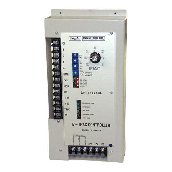
W-TRAC CONTROLLER DESCRIPTION TERMINAL LIST Terminal Description C1 Sensor common, and 0‐10Vdc reset common (‐). S 0‐10Vdc temperature reset input (+). D Supply air temperature sensor input. E Exhaust air temperature sensor input. A Outside air temperature sensor input. RMH 0‐10Vdc return air RH% input. EXH 0‐10Vdc exhaust air RH% input. MOD 0‐10Vdc heat wheel control output (+). C2 0‐10Vdc heat wheel control output (‐). +12 12Vdc output power +32 32Vdc output power (RH% sensor hot) T2(N) 24Vac Neutral power input. T1 24Vac Hot power input. 6 Output contact common 5 Output contact normally closed (N.C.) 4 Output contact normally open (N.O.). Start contact. ... -
Page 7: Indication And Diagnostic Lights
W-TRAC INDICATION AND DIAGNOSTIC LIGHTS On the face of the W‐TRAC are 5 red LED indication lights. Light Description Indicates the exhaust temperature is below the calculated minimum allowable Low Exhaust temperature, which is based on the amount of moisture in the return air (measured Temp or estimated) and the ambient temperature. Bad Sensor Shorted or open sensor indication. Vent Mode Wheel will be stopped. No call for heating or cooling. Discharge Too Hot Wheel is slowing down due to excessive recovery of heat. Frost Mode Heat wheel rotation speed is reducing to prevent frost accumulation. ADJUSTMENT POTS There are a number of setting and calibration potentiometers (POT’s) located on the face of the W‐TRAC. Modifications to these should only be done by experienced and qualified personnel. POT Description DIS CAL Discharge temperature sensor calibration. EX CAL Exhaust temperature sensor calibration. AMB CAL Ambient / outdoor temperature sensor calibration. BDRH Predicted design return air RH% scale (1‐4). TEMPERATURE CONTROL ... -
Page 8: Base Setpoint
W-TRAC If the outside air temperature is warmer than the exhaust air the W‐TRAC will enter ‘cool mode’ and rotate the heat wheel to transfer heat from the outside air to the exhaust. BASE SETPOINT The W‐TRAC is designed to be a discharge air temperature controller. The base discharge air temperature is set from the setpoint control knob located on the face of the W‐TRAC. SETPOINT RESET The base discharge air temperature is often modified from a remote signal to maintain the desired temperature of the supplied space. This is called reset. The W‐TRAC discharge temperature can be reset from a variety of sources using a 0‐10 VDC signal. An offset to the BMS input range can be implemented by adding a 7.5k resistor in series with terminal S. The following table describes the change of discharge setpoint from the input voltage (to terminals S + and C1 ‐), with a setpoint fixed at 66°F. Refer to the equipment function page for the design reset range. Input Voltage 0.0 2.0 4.0 6.0 8.0 10.0 Discharge No Resistor 30 / ‐1 40 / 4 45 / 7 52 / 11 60 / 15 66 / 19 Setpoint (°F/°C) 7.5k Resistor ... -
Page 9: Return Air Rh% Sensor
W-TRAC When the outdoor ambient temperature is below 15°F (‐10°C) the speed of the heat wheel will be reduced to maintain the leaving exhaust air humidity between 80 – 90%. This application requires high accuracy humidity sensors. RETURN AIR RH% SENSOR This method of frost control requires a RH sensor installed in the equipment return air section, just before the heat wheel, wired into terminals RMH and C2. DIP 3 must be ON, DIP 1 and 2 must be OFF. Using the values of the RH and ambient (outside air) sensor, the W‐TRAC calculates the minimum allowable exhaust air temperature that will keep frost from forming on the wheel. BDRH PREDICTED RETURN AIR RELATIVE HUMIDITY RH% sensing is not used in this method of frost control. DIP 1 and 3 must be ON, while DIP 2 is OFF. The W‐TRAC may operate without the use of humidity sensing in situations where the RH% values are expected to be reasonably constant. In these cases, the W‐TRAC operates by sensible temperature only. When enabled, the BDRH pot (Building Design Relative Humidity) is set according to the expected design return air conditions. Refer to the table below to set the expected values based on temperature and RH%. Table 1 Return Air Conditions BDRH setting 70°F (21°C) 75°F (24°C) 80°F (27°C) 1 < 25% < 21% < 18% 2 26 – 32% 22 – 27% 19 – 23% 3 33 – 39% 28 – 33% 24 – 27% ... -
Page 10: Service Notes
W-TRAC (over 50 ft. eq. length), the use of a minimum 20 gauge‐shielded wire is recommended. The shield should be grounded at the controller end only, with the other end taped. It is important to ensure correct polarity when wiring into the system. NOTE: Field analog control inputs require signal isolation to prevent ground loop signal corruption and/or damage to the controller(s). SERVICE NOTES ROTATION Most heat wheels have a purge section to purge exhaust air trapped in the wheel flutes before they rotate to the supply air side. The correct wheel rotation direction is noted on the face of the heat wheel. Drive motor rotation may be changed at the motor wire connections or on the inverter drive feeding the motor (if used). MOTOR SPEED CONTROL The modulating 0‐10Vdc motor speed output may be connected to a variety of controllers and/or inverters. Refer to the equipment wiring diagram for connection details. The following setup parameters are typical. Always refer to the equipment function sheet for any changes. To ensure proper setup operation, do not have DIP 4 and DIP 5 on at the same time. KBVF / SIVF(R) The KBVF inverter drive and SIVF signal isolator are manufactured by KB Electronics Inc. The inverter and isolator installation and operation manuals are included in the information package, originally located in the main equipment electrical panel. The 0‐10Vdc W‐TRAC control output feeds into the SIVF signal isolator which, in turn, feeds an isolated 0‐5Vdc signal to the KBVF inverter drive. High Speed Turn on W‐TRAC DIP 4 to force the W‐TRAC to maximum output (near 10Vdc). Note that if the W‐TRAC is operating in frost mode DIP 4 will not allow the drive to go to full speed. Measure the motor amps and confirm the readings are less than the maximum motor ampacity. If possible, measure and confirm the output frequency is 60Hz. The KBVF is factory set to 100% of rated frequency (60Hz) and should not be adjusted. ... -
Page 11: Wheel Rotation Speed
W-TRAC Low Speed Turn on DIP 5 to drive the output to minimum (0Vdc). Adjust the minimum speed pot on the KBVF inverter drive until the heat wheel just begins to turn, usually between 0.5 and 2 rpm. Turn the power off, and then restart the system to confirm the motor has enough starting torque to reliably start rotating the heat wheel. Return all DIP switches to their original position. WHEEL ROTATION SPEED Maximum wheel rotation speed will be factory set in the range of 30‐40 rpm, at 60 Hz, depending on the size of the heat wheel. Minimum wheel speed is dependent on the starting torque of the motor and heat wheel, usually between 0.5 and 2 rpm. SENSOR CALIBRATION Discharge Temperature Calibration Remove the supply air temperature sensor and measure both the sensor resistance and the temperature at the sensing element. Compare these readings to the sensor table values. If the resistance is out by more than 16 ohms, replace the sensor. Measuring a sensor temperature between 60 – 70°F, slowly rotate the temperature setpoint dial counter clockwise until the ‘Discharge Too Hot’ light just comes on. Slowly increase the temperature setpoint dial until the light goes off. The setpoint should match the sensed temperature measurement. If not, adjust the calibration pot and repeat test. Exhaust Temperature Calibration Remove the exhaust air temperature sensor and measure both the sensor resistance and the temperature at the sensing element. Compare these readings to the sensor table values. If the resistance is out by more than 16 ohms, replace the sensor. The ‘bad sensor’ LED may turn on and off during this procedure. Place a jumper wire across terminals A and C1. Remove the exhaust temperature sensor and replace with a 909 Ω resistor. ... -
Page 12: Humidity Sensors
W-TRAC Slowly rotate pot #2 counter clockwise (EX CAL)) until the low exhaust temperature light comes on. Slowly rotate pot #2 clockwise until the low exhaust temperature light just turns off. Reconnect all sensors and set pot BDRH back to its original position. Humidity sensors Accurately measure the relative humidity at the sensor location and compare to the sensor Vdc output. The 0‐10Vdc output is proportional to 0‐100% RH. SENSOR TABLE Sensor Resistance Chart for TE6000EA3 Table 2 °C °F Resistance °C °F Resistance °C °F Resistance ‐40 ‐40 602 18.3 65 983 48.9 120 1234 ‐34.4 ‐30 633 20 68 996 ...
Need help?
Do you have a question about the EngA W-TRAC and is the answer not in the manual?
Questions and answers