Table of Contents
Advertisement
A
INSTALLATION, OPERATION
AND MAINTENANCE MANUAL
FOR
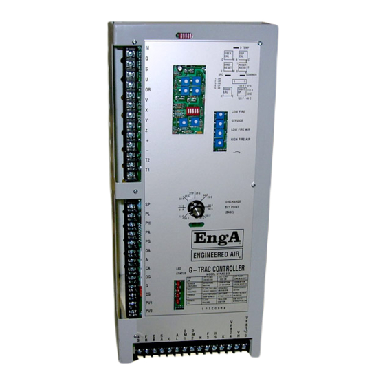
G-TRAC2
INDIRECT FIRED HEATING CONTROLLER
UNIT MODEL NO. _________________
UNIT SERIAL NO. _________________
SERVICED BY: ___________________
TEL. NO: ________________________
CANADIAN
USA
CANADIAN
HEAD OFFICE
HEAD OFFICE
EASTERN FACTORY
AND FACTORY
AND FACTORY
rd
1401 HASTINGS CRES. SE
32050 W. 83
STREET
1175 TWINNEY DRIVE
CALGARY, ALBERTA
DESOTO, KANSAS
NEWMARKET, ONTARIO
T2G 4C8
66018
L3Y 5V7
Ph: (403) 287-4774
Ph: (913) 583-3181
Ph: (905) 898-1114
Fx: 888-364-2727
Fx: (913) 583-1406
Fx: (905) 898-7244
SALES OFFICES ACROSS CANADA AND USA
Retain instructions with unit and maintain in a legible condition.
Please give model number and serial number when contacting
factory for information and/or parts.
www.engineeredair.com
IOM-25
Mar 99 R7
Advertisement
Table of Contents

Related Manuals for Engineered air EngA G-TRAC2


Summary of Contents for Engineered air EngA G-TRAC2
- Page 1 INSTALLATION, OPERATION AND MAINTENANCE MANUAL G-TRAC2 INDIRECT FIRED HEATING CONTROLLER UNIT MODEL NO. _________________ UNIT SERIAL NO. _________________ SERVICED BY: ___________________ TEL. NO: ________________________ CANADIAN CANADIAN HEAD OFFICE HEAD OFFICE EASTERN FACTORY AND FACTORY AND FACTORY 1401 HASTINGS CRES. SE 32050 W.
-
Page 2: Table Of Contents
G-TRAC2 TABLE OF CONTENTS APPLICATION ..................................6 SERVICE .................................... 6 III. RESET DISCHARGE AIR TEMPERATURE ........................... 6 GENERAL DESCRIPTION ..............................6 ....................................6 PERATION ................................... 7 ASIC EATURES WIRING .................................... 7 SYSTEM TIMINGS................................8 VII. BLOWER AIR AND GAS MODULATION ..........................8 VIII. - Page 3 G-TRAC2 XVIII. ROOM RESET THERMOSTAT OPTIONS........................17 )....................18 ODULATING ESET CONTINUOUS BLOWER OPERATION ONLY ......................21 ALCULATED ISCHARGE ABLE FOR OOM AND MBIENT ESET ................................22 ULTIPLE ENSORS BMS R ) ............................22 ESET ONTINUOUS BLOWER ONLY BMS R –...
- Page 4 G-TRAC2 “D ” S ........................40 REPURGE IGHT TAYS AMPER OVING TATUS G-TRAC2 ............................. 40 EPLACING A IN THE IELD G-TRAC2 ..........................42 HANGING AS OR PERATOR ON XXV. MISCELLANEOUS NOTES ............................42 IOM-25 4 of 42 Mar 99 R7...
- Page 5 G-TRAC2 IOM-25 5 of 42 Mar 99 R7...
-
Page 6: Application
(BMS), etc., are in use. If used, refer to appropriate reset information in this guide. GENERAL DESCRIPTION The G-TRAC2 is a programmed logic controller designed for use with the Engineered Air DG series heaters. This control package provides temperature, supply blower, and burner control. The G-TRAC2 eliminates the mechanical linkages between the combustion air and gas actuator by using direct drive floating point. -
Page 7: Basic Features
G-TRAC2 value can be read at the terminals provided (See Section XVIII). The G-TRAC2 will modulate/cycle the burner as needed to maintain discharge air temperatures. Basic Features Standard service and testing features such as status indicating LED’s, service pot, and temperature test points. Proportional and Integral (PI) discharge air temperature control. -
Page 8: System Timings
G-TRAC2 SYSTEM TIMINGS Pre-purge 75 seconds at 85% opening Maintained purge 5 minutes Supply fan start delay (damper open time) 64 seconds Heat exchanger warm up time 64 seconds Burner cool down time 60 seconds Heat exchanger cool down time 1 min (except on low limit failure) Flame fail Usually 15 seconds (it is set by flame relay) -
Page 9: Dip Switch Block B - Fuel Curves/Air Curves
G-TRAC2 Dip switch Block B – Fuel Curves/Air Curves The GTRAC-2 has built in air to fuel ratio curves. The combination of these curves provides 16 possible settings. The curves are selected by turning dipswitches on or off. These dipswitches are located in a slot below the set-point knob on the front of the control. -
Page 10: Pots
G-TRAC2 NOTE : XXX Switch position does not affect description in “ACTION” box. ACTIONS Low limit active. * Low limit disabled. * NORMAL OPERATION (PI control). (No BMS on C-TRAC direct control but may be reset control) Direct C-TRAC3 control (reduced integral control). @ Direct BMS 010 VDC control (proportional control only).... -
Page 11: Led 2 Heat Required
G-TRAC2 Irregular Flash The combustion blower is off but the combustion air-proving switch is closed or shorted. This indicates a wiring, set up, or part failure problem. Fast Flash The actuators controlling the air and gas are not in the correct position for pre-purge or ignition. The G- TRAC2 is attempting to reposition the motors. -
Page 12: Auto Bypass Low Limit
G-TRAC2 AUTO BYPASS LOW LIMIT NOTE: Low limit can be disabled (Dipswitch C-5). The low limit set point is fixed at 40ºF. There are two low limit bypass timers, start-up and anti noise. The 6 minute start-up auto bypass low limit timer is started every time the night terminal energized status changes (on-off or off-on transition) or when the "SA"... -
Page 13: Fan Damper At Night (Terminal "K" Powered)
G-TRAC2 The values for “FS and HS”, service switch and flame supervision device are noted on the following table. Terminal “K” is OFF (not powered) for this “Daytime Operation Table”, thus the control is operating in day mode. Dipswitch A-4 determines supply fan configuration (as noted above). -
Page 14: Basic Burner Operation
G-TRAC2 Damper operation depends on fan switch position “ON”. This opens dampers when the supply fan is on. Configure Dip Switch 1-4 Configure Dip FS Fan Service Flame NOTE Heat OPEN Switch 1-4 CLOSED Terminal K Limit Fail Temperature Air Flow Priority Priority Unit locked off Unit locked off on... - Page 15 G-TRAC2 The following is a flowchart covering many general operating/troubleshooting situations. If a more detailed manual is needed, contact the nearest EngA factory. BASIC BURNER OPERATION FLOW CHART Is there a heat G-TRA2 should required light move There is no on indicating a call for call for heat?
-
Page 16: Heat Required Led On
G-TRAC2 Heat Required LED ON Upon a call for heat, the “Heat Required” LED light will come on. Pre-Purge Light PRE-PURGE LITE ON When the combustion air actuator is in the correct position, the air-proving switch will close and the “pre-purge” light and timer will start. -
Page 17: Temperature Control - General Overview
G-TRAC2 XIV. TEMPERATURE CONTROL – GENERAL OVERVIEW The G-TRAC2 is primarily a “discharge air control”. Optional discharge reset devices and night heat packages are available. Refer to unit wiring diagram and/or GTRAC-2 dipswitch label to see how your unit is equipped. Wires to G-TRAC2 OPTION M,S,U... -
Page 18: Modulating Room Reset (Continuous Blower Operation Only)
G-TRAC2 Additional technical information is also located under "Staged Resets and Overrides". NOTE: When any override is calling, it will affect the "Calculated Set Point" and its relation with the "Temperature Readout". It is recommended that the service technician be very familiar with these two sections of the manual. - Page 19 G-TRAC2 as per both the setting of pot 5 and the discharge set point. The calculated discharge air set point (dial setting + reset) is limited between 48°F and 120ºF. To determine the amount of reset available use the following chart (See page 21). EXAMPLE: G-TRAC2 set point 70°F Reset Ratio Pot set at 3 (total reset 29°: +18 is upper reset limit, -11 is lower reset limit)
- Page 20 G-TRAC2 Diagram C Same as Diagram A but wider reset range because Pot 5 set at 5. Discharge Operating Range 48°F 120°F Absolute lowest Absolute highest Upper reset limit allowed discharge allowed discharge set Manual Set point Lower reset limit set point point Ex 70°F...
-
Page 21: Calculated Discharge Table For Room And Ambient Reset
G-TRAC2 Calculated Discharge Table for Room and Ambient Reset ROOM RESET AMBIENT RESET Max. Discharge Min. Discharge Max. Discharge Min. Discharge Total Temp. (when Temp. (when Temp. (when Temp. (when Band room calls for room is too ambient is <15ºC) ambient is >70ºF) Width heat) -
Page 22: Multiple Room Sensors
G-TRAC2 TE6000 TE6000 Grey Orange TE6000 Blue Built in TE6100 Sensor Element Violet Multiple Room Sensors Four sensors can be wired to give an average reading of room temperatures to the TRAC control. They must be wired in a series/parallel arrangement. The drawing above drawing shows a circuit making use of the built in sensor in the TE6100 Johnson Sensor/Setpoint assembly and using TE6000 sensors for the other three. -
Page 23: Bms Reset From Voltage Applied To + And
G-TRAC2 BMS Reset from Voltage Applied to + and – Calculated Set-Point Reset Voltage (VDC) ºC ºF 13.5 14.5 Approximate relationship between 0-10 VDC and 4-20 ma signals is: Note: zero reset less than 2 VDC or less than 1 ma BMS Calibration Apply 20 ma or 10 VDC signal to the G-TRAC2 ‘+ and ’... -
Page 24: Make/Break Resets And Overrides
G-TRAC2 Ambient Based Discharged Air Set Point Reset Curves Maximum Up Reset Warmer Set Point Ambient Temperature No Reset 20°F 80°F 0°F 40°F 60°F -20°F Maximum Down Reset Cooler In order for the discharge air temperature to go from zero reset to maximum reset, (up or down) the ambient temperature has to change by 40°F. -
Page 25: X" And "Z" Override (Day And Night Operation)
G-TRAC2 Note that if this system is to be used as a night heat package with the room temperature being set back to a lower value then that used in the daytime, this system would require a separate night thermostat and a device switching between the day and night thermostats. - Page 26 G-TRAC2 NOTE: When the room thermostat calls while operating in night mode, a modulating high limit feature built into the G-TRAC will not allow the discharge temperature to exceed the setting of the night SP pot (100° - 120°F), if the unit’s heating capacity will allow temperatures to rise that high. During the night cycle when the G-TRAC's ter and common, will not be correct.
-
Page 27: Linear Ambient Reset (During Day And Night) - Room Control With Intermittent Blower (During Night)
G-TRAC2 HOT 120 OR 24 NEUTRAL FAN SW HOT 24v NIGHT SIGNAL CONTACT Air Flow Switch IGN. CONTROL 24 V SUPPLY POWER COMBUSTION MOTOR 3. Linear Ambient Reset (During day and night) – Room Control with Intermittent Blower (During night) During day operation the discharge temperature will be linearly reset based on the ambient temperature. -
Page 28: Vdc Control
G-TRAC2 GTRAC-2 0 – 10 VDC Control To prevent false lockouts from the low limit or open temperature sensors, the G-TRAC2 must have a temperature sensor or a jumper must be placed across the G-TRAC2 terminals Q and U. The G-TRAC2 will receive its control signal from the C- TRAC or Metasys control. -
Page 29: Discharge Temperature Readout
G-TRAC2 SET-POINT READOUT AND DISCHARGE TEMPERATURE FROM VOLTAGE ON READOUT PINS Voltage (VDC) ºC ºF DISCHARGE TEMPERATURE READOUT The discharge temperature at the temperature sensor can be obtained by measuring the voltage across spade connector terminals “DTEMP” to “COMMON”. The readings are based on 10ºC per volt. (Example: A reading of 2.15 volts = 21.5ºC.) ACTUAL TEMPERATURE READOUT FROM VOLTAGE ON READOUT PINS Voltage (VDC) ºC... -
Page 30: Te6000 Discharge Sensor Self-Test
G-TRAC2 TE6000 Discharge Sensor Self-Test If the discharge sensor resistance is greater than 4000-ohms or less than 880-ohms, the unit will lock out either on low limit or bad temperature sensor. The G-TRAC2 will not operate with a bad discharge sensor. If the G-TRAC2 locks out due to an open discharge sensor LED 3 will flash rapidly. -
Page 31: Johnson Set-Point
G-TRAC2 Johnson Set-Point Adjust DSP CAL until the SPC voltage reading matches the dial set point value divided by 10° will give VDC. Return the dipswitches to their normal position. Built In Set-Point Loosen the setscrew on the set-point knob and move the knob until the dial set point agrees with the measured set-point value. -
Page 32: G-Trac2 Set Up Sheet
G-TRAC2 XXII. G-TRAC2 SET UP SHEET Rev. OCT/08 Job #_________Tag #__________Designer________Model #______________Date_________ BASE SETPOINT LOCATION G-TRAC2 ________ or Remote ________ Base discharge set point *_____________ degrees F *Set point is not required when GTrac-2 is DIRECT controlled by other controllers. ROOM RESET [YES] __________ [NO] ___________ (dipswitch A-3) -
Page 33: Burner Set Up
G-TRAC2 XXIII. BURNER SET UP Operator Control Rules The G-TRAC2 provides separate independent control loops for the gas and air operators. Each operator has a position feedback set point and deadband. The control deadband is the allowable operator position error (actual position versus set point) before the operator is repositioned. -
Page 34: Combustion Set Up
G-TRAC2 Combustion Set Up Pot Position Fine Tuning (Low Fire Rate, Low Fire Air) Adjusting the trim pots may, at times seem to have no effect, but turning the pot just a little more will move the operator a large step. For some applications this step may be too large. If this happens there is a method to get the G-TRAC2 to recognize small or partial step movements. - Page 35 G-TRAC2 4. High Fire Gas and Air A. Place the unit into the service mode (dipswitch A-5 on) and power up the G-TRAC2 terminals “T1 and T2” and the air/gas operators. B. (Initial Operator Wiring Pre-Check) With power to the FS terminal "off", but power to the actuators "on": ...
- Page 36 G-TRAC2 Properly adjusting the low fire air is the most difficult step in the set up process. The low fire air is meant to be set by an initial mechanical adjustment followed by fine-tuning on the low fire air pot. For the initial factory adjustment, place the low fire air pot to mid-scale.
-
Page 37: Inlet/Manifold Pressure Settings
G-TRAC2 Inlet/Manifold Pressure Settings Manifold pressure settings that the unit was tested and clocked at in the factory are recorded on the unit rating plate. Any attempt to clock a unit in the field should be done with care. Corrections for density (altitude and station pressure), temperature, and the correction factor for the meter are often overlooked, thus leading to an incorrect conclusion. -
Page 38: Air Balancing (Refer To Next Item)
G-TRAC2 Air Balancing (Refer to next item). Cold Discharge Temperature in Cold Weather Installation and air balancing is often done during warmer weather than that experienced in the cold of winter. If the air balancer did not allow for the changes that will occur in air volume in cold weather then the unit will appear to be short of temperature rise. -
Page 39: Regulator Gas Pressure Responses
G-TRAC2 Usually changing the pilot assembly will not have much of an affect on the pilot signal if both assemblies are in good condition and installed correctly. 10. Ensure the pilot assembly gasket is tightly installed to stop air leakage into the pilot area. 11. -
Page 40: Burner Pulsing, Backfiring, Exploding, Noisy
G-TRAC2 form. Combustion that is set at maximum efficiency will produce excess moisture. Often it is desirable to have 1% to 2% higher excess oxygen readings then those normally listed to assist in keeping the flue gases drier. Also note that extended chimneys can contribute to condensation problems (especially if they are not insulated or at least double walled). - Page 41 G-TRAC2 NOTE: If the following information is not recorded on the G-TRAC2 configuration label attached to the control cabinet wall, any time you see any G-TRAC2 equipped unit, you should record these voltages on the wall of the control cabinet for later use in case the G-TRAC2 ever fails. Before changing a G-TRAC2, if possible you should have the unit in operation and record the following information so that you may make the change quickly and avoid a time consuming combustion set up.
- Page 42 G-TRAC2 Changing Gas or Air Operator on G-TRAC2 1. The motors are usually not at the end of the stroke when you approach the problem of changing one. They will usually, at best, be in the “Start” position, which will be with about a 5-degree stroke position for the combustion air actuator.
Need help?
Do you have a question about the EngA G-TRAC2 and is the answer not in the manual?
Questions and answers