Table of Contents
Advertisement
Advertisement
Table of Contents

Subscribe to Our Youtube Channel
Related Manuals for GEISMAR Amber


Summary of Contents for GEISMAR Amber
- Page 1 Document No. GUK0018/2007 issue 02...
- Page 2 Document No. GUK0018/2007 issue 02 2 of 53...
- Page 3 The information, drawings and any other descriptive matter set out in this publication are the confidential and copyright property of Geismar (U.K.) Limited and must not be disclosed, loaned, copied or used for any manufacturing, tendering or for any other purpose without their written permission.
-
Page 4: Table Of Contents
Operating Manual for GEISMAR Amber Manual Track Geometry Recording Unit Contents General Introduction ......................6 Specification and measuring Parameters ..............7 2.1Metric (Standard Gauge) ....................7 2.2Imperial (Standard Gauge) ................... 8 2.3Metric (Narrow Gauge) ....................9 2.4Imperial (Narrow Gauge) ..................... 10 Principal components of the Amber unit ................ - Page 5 Operating Menu sequence ................37 Operating Menu function descriptions ............39 Tolerance Profiles (Administrator and Supervisor levels only) ....42 Creating a profile................... 42 Editing a Profile ..................43 8.2.1 Copying a Profile ................43 8.2.2 Editing a Profile ................43 Dealing with profile conflicts ...............
-
Page 6: General Introduction
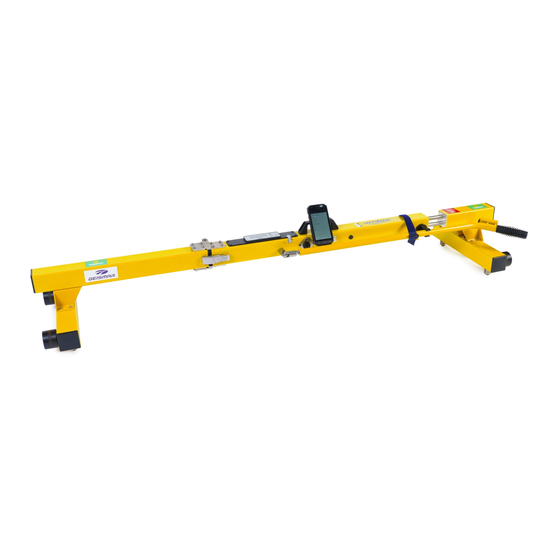
1.0 General Introduction The Amber is a battery powered compact manual track geometry recording unit. It is designed for the continuous measurement of gauge, cross level, distance and twist over two different twist bases. Two design versions are available:- Folding single piece unit with integral push handle for gauges of 1100mm and above. -
Page 7: Specification And Measuring Parameters
2.0 Specification and measuring Parameters Metric (Standard Gauge) Measurements Gauge: - -20 to +50 mm datum set at 1435mm Measurement accuracy:- +/-1mm Cross Level (Cant):- +/-200 mm Accuracy:- +/-1mm over 0-200mm Track Twist: - +/-100mm Measurement accuracy:- +/-1.5 mm Twist 1 base length :- adjustable in 0.125m steps Twist 2 base length :- adjustable in 0.125m steps... -
Page 8: Imperial (Standard Gauge)
Imperial (Standard Gauge) Measurements Gauge: - - 0.75 to +2.0 mm datum set at 58.5 Measurement accuracy:- +/- 0.04 Cross Level (Cant):- +/- 8.0 Accuracy:- +/- 0.04 over 0 Track Twist: - +/- 4.0 Measurement accuracy:- +/- 0.06 Twist 1 base length :- adjustable in 0.125yd steps Twist 2 base length :- adjustable in 0.125yd steps... -
Page 9: Metric (Narrow Gauge)
Metric (Narrow Gauge) Measurements Gauge: - -20 to +50 mm datum set at 597mm Measurement accuracy:- +/-1mm Cross Level (Cant):- +/-90 mm Accuracy:- +/-1mm over 0-200mm Track Twist: - +/-100mm Measurement accuracy:- +/-1.5 mm Twist 1 base length :- adjustable in 0.125m steps Twist 2 base length :- adjustable in 0.125m steps Exceedance settings... -
Page 10: Imperial (Narrow Gauge)
Imperial (Narrow Gauge) Measurements Gauge: - - 0.75 to +2.0 mm datum set at 23.5 Measurement accuracy:- +/- 0.04 Cross Level (Cant):- +/- 3.5 Accuracy:- +/- 0.04 over 0 Track Twist: - +/- 4.0 Measurement accuracy:- +/- 0.06 Twist 1 base length :- adjustable in 0.125yd steps Twist 2 base length :- adjustable in 0.125yd steps... -
Page 11: Principal Components Of The Amber Unit
3 Principal components of the Amber unit Folding Unit Mains charger charging socket Item No Description Folding unit Amber Main Unit Hinge Clip Push Handle Assembly 1 x Handle retaining strap 1x Handle retaining clip Wheel Assembly Contact Roller Assembly Carry Handle Assembly Document No. -
Page 12: Fixed Length Unit
Fixed Length Unit Tacho wheel Mains charg er charging socket Item Description Fixed length unit Amber Main Unit Not Applicable Push Handle Assembly Detachable Handle retaining straps Handle retaining clips Wheel Assembly Contact Roller Assembly Carry Handle Assembly Tacho wheel Document No. -
Page 13: Amber Unit Control Buttons
Amber unit control buttons Button A - (lightning flash) switches the unit on. To operate depress and hold until the word discoverable appears as pic below and note the battery level indicator. Button B (thumbs up) switches the unit off but only following a data recording run. -
Page 14: Amber Unit Event Buttons
Amber Unit event buttons The Amber unit incorporates a programmable 3-button event marker for speedy recording of pre selected events whilst carrying out a recording run. Pressing any of the buttons will store the relevant event comment(s) in the data files. -
Page 15: Operation Of The Hand Held Pc Software
Each unit is provided with its own PDA (hand held PC) incorporating a touch screen display using the stylus provided. Each PDA is paired to work with a specific Amber unit and none other. To change this refer to Para10.0 section on Pairing Operating the menu screen Paragraphs 6.0 and 7.0 provide a menu layout and a detailed description of... -
Page 16: Using The On-Screen Key Board
Using the on-screen key board. Any keyboard or virtual keyboard provided on the PDA will be disabled when used in conjunction with the Amber. In order to input information, values or comments etc the Amber software provides its own virtual QUERTY keyboard. -
Page 17: Working Off Line Or On Line
Amber unit may be elsewhere or being charged (NB please note that it is not possible to work On Line whilst the Amber unit is being charged). To operate Off Line simply switch on the hand held PC and select the Amber short cut. -
Page 18: Set Up And Recording Procedure
Fig 2 Fig 3 A folding Amber unit should be carried as fig 1 when in its folded position. Always ensure that the push handle is stored in the retaining clip and that the handle retaining strap is in position and fastened before carrying in the folded position. - Page 19 Fig 5- carrying position for a fixed length unit. Fig 4 carrying position for folding unit when set up To set up on track place the unit in the four foot (position the unit in the opposite direction of planned travel if the cant rezero calibration is to be carried out as this will save a little time).
- Page 20 Folding amber Unit on track Fixed length unit on track with push handle screwed in to position When on track wait 45 seconds to allow the unit s electronics to stabilise and then the unit is ready for track recording setting up. When set up as described in Para 5.2 push...
-
Page 21: Track Recording Setting Up
5.2.1 Switching on - Unit and hand held PC(PDA) Set up the unit for recording by following the sequence below:- (01) Press the flash button on the Amber unit and hold down until the word discoverable is visible on the LCD screen. - Page 22 (06) and (07) Scroll to Cant Rezero. If current temperature is coloured red select Cant Rezero if green scroll to System Status. To proceed with the Cant Re-zero procedure, ensure that the Amber gauge is on track (track can be canted) but avoid any of the wheels resting on a joint.
- Page 23 (10) Confirmation that calibration (11) Scroll to System Status Is completed. Select OK 12) Shows battery status of the unit. (13) Scroll to Open Job, tap drop Colour red denotes 25% capacity down menu, select New and tap Open Job window. Document No.
- Page 24 (14)Click down arrow for Route ID (15) Make selection and repeat for other reference items If a required description does not exist in the drop down menu, select New . This will cause the virtual keyboard to appear (see Para 4.2). The required description can be typed in and will be stored automatically for future reference.
- Page 25 (16) Scroll to Start Location (17) Enter details, select Km or Miles/Yds, chose Increment decrement. Tap the dialogue screen to call up the virtual key board to enter large values. See Para 4.2 for keyboard operation (18) Scroll to Tolerance Profile and (19) Choose Tolerance Profile and scroll to Start Job tap drop down arrow...
- Page 26 Green = OK, Amber = Level 1 fault and Red = Level 2 fault. Note that the battery indicator bar which will reduce in length as the battery level reduces. When this changes to RED battery level has 25% capacity remaining.
- Page 27 In addition to the visual indication on the acquisition screen of any exceedances, there will also be an audible alert from the actual Amber unit. In instances of faults occurring briefly it is likely that the walking speed of the operator will have taken them past the fault.
-
Page 28: Closing The Job
5.2.2 Closing the Job (01) Select Pause (02) Select down arrow (03) Make a selection regarding the (04) Select Close Job Job details. This does not affect the data which is saved automatically. Document No. GUK0018/2007 issue 02 28 of 53... -
Page 29: Updating Location
(05) Scroll to Exit Software (06) Select exit software On exiting the software, the PDA will revert to the normal start screen. The Amber unit alarm will bleep continuously and will require switching off by pressing the thumbs up button. -
Page 30: Adding Existing Comments
(03) Change the values with the+/- keys or call up the key board see Para 4.2 Press, hold and release the Update button to return to acquisition screen or scroll to another item. 5.2.4 Adding existing comments (01) Select Pause (02) Scroll to Add Comment Document No. - Page 31 (03) Select down arrow (04) Select option (05) Select and Add Comment(s) (06) Selection confirmed Press, hold and release the ADD Comment button to return to acquisition screen or scroll to another item. Document No. GUK0018/2007 issue 02 31 of 53...
-
Page 32: Creating A New Comment
5.2.5 Creating a new comment (01) Select Pause (02) Scroll to Add Comment (03) Select down arrow (04) Select New Document No. GUK0018/2007 issue 02 32 of 53... - Page 33 (04) Type in New Comment (06) Tap Save (07) Tap Add comment (08) Comment confirmed. Tap, hold and release the ADD Comment button to return to acquisition screen or scroll to another item. Document No. GUK0018/2007 issue 02 33 of 53...
-
Page 34: Cant Re-Zeroing Whilst Collecting Data
5.2.6 Cant re-zeroing whilst collecting data If the temperature indicator on the Acquisition screen is or becomes red it will be necessary to carry out a re-zeroing procedure. From menu select <Pause> - <Cant Rezero> - measure A-B <Start> - Measure B-A - <Start>... - Page 35 (03) Scroll to Job Management (04) Confirm selection and select -delete (05) If Copy is selected the complete job profile will be copied and displayed in the job settings together with a time stamp to differentiate it from the original. Selecting <Open Job>...
-
Page 36: System Security - Using Your Password And Operator Id
The Log in screen (Para 5.2) requires an Operator ID to be entered before connection between the PDA and amber unit can be made. As referred to in Para 6.0 there are within the Amber software several menu screens. The System Security level selected will determine which menu items will be displayed. -
Page 37: Operating Menu Sequence
Operating Menu sequence There are within the Amber software several menu screens. Depending upon the security level of the operator and whether the Amber unit is switched on or not will determine which menu items will be displayed. Refer to Para 7.0 for a full description of the individual menu items and security availability. - Page 38 <Edit Tolerance Profile> <Profile ID> <Profile Security> Locked/unlocked <Gauge L1 Tolerance> <Gauge L2 Tolerance> <Cant L1 Tolerance> <Cant L2 Tolerance> <Cant L1 Tolerance> <Twist Base> <Twist1 L1 Tolerance> <Twist1 L2 Tolerance> <Twist2 L1 Tolerance> <Twist2 L2 Tolerance> <Profile Management> <Settings> <Acquire Rate>...
-
Page 39: Operating Menu Function Descriptions
Cancels the procedure <Connect>§ When working with the Amber unit switched off (Off Line) allows connection to the Amber unit without having to exit and restart the software. The Amber unit MUST be switched on before connecting. <Open Job> Shows existing job profiles and access to modifying or creating new jobs <Job Reference>... - Page 40 For carrying out rezeroing see Paras 5.2.3 and 6.2.4 <System Status> Displays design data including battery status of the Amber unit only. <Edit Tolerance Profile> Displays the tolerance profile options which are (i) Select and view an existing profile for the job (ii) select and modify an existing profile (See Para 8.0 for modifying an...
- Page 41 Exits the application and hand held PC display reverts to normal start screen. The Amber unit will bleep continuously if switched on to confirm that the exit has been completed. To switch off press the thumbs up button on the Amber unit.
-
Page 42: Tolerance Profiles (Administrator And Supervisor Levels Only)
Tolerance Profiles (Administrator and Supervisor levels only) Creating a profile Select short cut to amber <Operator ID> enter/select ID <System Security> enter password. Tap <Start> Scroll to <Edit Tolerance Profile> Highlight New from drop down menu and tap <Edit Tolerance Profile>... -
Page 43: Editing A Profile
There are two methods of editing a profile. (a) Creating a profile similar to an existing one by copying the existing one and modifying it (b) changing or updating an existing profile and retaining its original name by editing. 8.2.1 Copying a Profile Select short cut to amber <Operator ID> enter/select ID <System Security>... -
Page 44: Updating Profiles To Other Users
When the new Job with the latest Tolerance Profile has been created exit the Amber software and revert to the PDA normal operating screen and proceed as below:- <Start > <File Explorer> <My Device > <SD Card> <Job Files >... -
Page 45: Data Collection And Transfer
Data collection and transfer Data collected is stored on the PDA in a file called SD Card. Two files are produced (i) Measurement Data which contains all the data and comments collected from the recording run and (ii) Exceedance Data which contains only data where there is a geometry exceedance which will be shown in colour blue or red and any comments and events also recorded and highlighted in red. -
Page 46: Typical Measurement Data
9.1 Typical Measurement Data Route ID ELR 123 Track ID Up Fast Job Comment Weekly Start Location 256 Miles 2 Yards Direction Increment Operator ID Alan Leyland System Security Operator Start Time 10h49m28s-09Mar2007 End Time 11h11m00s-09Mar2007 Start/End Temperature 22°C / 23°C Rezero Temperature 18°C Calibrated... -
Page 47: Typical Exceedance Data
9.2 Typical Exceedance Data Route ID ELR 123 Tr ack ID Up Fast Job Com m e nt Wee kly Start Location 256 M iles 2 Yards End Location 256 M iles 18 Yards Dir ection Incr em e nt Operator ID Alan Leyland Sys te m Se curity... -
Page 48: Pairing
However in the event that it is necessary for a PDA to work with another Amber unit or if the Bluetooth link is lost it will be necessary to carry out Bluetooth pairing. - Page 49 Spot checks of calibration can be carried out whenever required by placing the Amber recording unit on a track at various locations where the track parameters are known. If a fault is suspected in the calibration, the instrument must be returned to GEISMAR (UK) Limited for a full calibration check and recalibration as necessary.
-
Page 50: Battery Management And Charging
Charging a unit should be completed in 24 hour but do not keep on charge for longer than a week end. The Amber unit should not be charged in ambient temperatures exceeding 30ºC. (NB please note that it is not possible to work On Line whilst the Amber unit is being charged) ReportingFaults Should you experience any problems with the operation of your Amber unit please contact us as detailed on page 2. -
Page 51: Confidentiality Notice
Reproduction of any or all of this document is strictly forbidden without the prior written approval of Geismar. The manual is an essential part of the Amber track geometry recording system and should be kept for the lifetime of the unit. Any amendments or modifications to the manual provided by Geismar must be kept with it and/or included in the manual itself. - Page 52 Should you have any questions concerning this Agreement, or if you desire to contact Geismar for any reason, please contact Geismar Customer Sales & Service, Geismar (UK) Ltd, Salthouse Rd, Brackmills...
- Page 53 Document No. GUK0018/2007 53 of 53...
Need help?
Do you have a question about the Amber and is the answer not in the manual?
Questions and answers