Table of Contents
Advertisement
Quick Links
Advertisement
Table of Contents

Related Manuals for BONFIGLIOLI DGM

Summary of Contents for BONFIGLIOLI DGM
- Page 1 User instructions. DGM speed regulator...
- Page 2 Exclusion of liability All the names used, commercial names, product names or other names may be legally protected even if not specially indicated (e.g. such as logos). BONFIGLIOLI does not assume any liability or guarantee for their free use. Maximum care was taken when preparing the images and texts. However, it is not possible to exclude the presence of errors.
-
Page 3: Table Of Contents
Selection of the model ....................22 2.1.2 Division of the sizes ....................23 MMI*/connection cable PIN assignment ..............24 Description of the DGM speed regulator ..............25 Installation ..................26 Safety instructions for installation ................26 Recommended fuses/automatic circuit breaker ............26 Installation requirements ................... - Page 4 Power connection...................... 75 3.5.5 Brake chopper connections ..................76 3.5.6 Control connections X5, X6, X7 ................. 76 Deinstalling and installing the DGM fan size “D” ............76 3.6.1 Deinstalling the fan ....................77 3.6.2 Installing the fan ......................79 Start-up .................... 82 Safety instructions for start-up ...................
- Page 5 Adapter plates ......................157 9.1.1 Adapter plates for a generic motor ................157 9.1.2 Bonfiglioli motor adapter plates ................160 9.1.3 Wall adapter plates (standard) ................161 Foil keypad ......................164 Hand-held MMI control device incl. 3 m of RJ9 connection cable to the M12 connector ..........................
-
Page 6: General Information
DGM. We do not accept any liability for damage caused by the failure to follow these instructions. This manual is an integral part of the product and applies only to the DGM manufactured by Bonfiglioli Riduttori S.p.A. -
Page 7: Warnings Related To These Instructions
Disconnect the electrical voltage from the speed regulator and secure it to prevent it from being reconnected. Fig. 1: Structure of the warnings Warning symbol Keyword Type of hazard and relative origin Possible consequence if not observed Solution User instructions. DGM speed regulator... -
Page 8: Warning Symbols Used
This indicates a threat with a medium degree of risk that, if not avoided, results in death or serious injuries. CAUTION This indicates a threat with a low degree of risk that, if not avoided, could cause moderate injuries or material damage. User instructions. DGM speed regulator... -
Page 9: Information Notes
Fig. 2: Example of an information note S ymbols used in the infor mation notes Important information Material damage is possible Other notes INFORMATION Image enlarged User instructions. DGM speed regulator... -
Page 10: Symbols Used In These Instructions
Consecutive steps of user instructions Implications of the user instructions ✓ Final result of the user instructions List Fig. 3: Utilized symbols and icons Utilized abbrevia tions Abbreviation Explanation Table Table Fig. Figure Pos. Position Chap. Chapter User instructions. DGM speed regulator... -
Page 11: Marks On The Speed Regulator
Plates and marks are applied on the speed regulator. Do not change or remove them. Symbol Meaning Risk of electric shock and electric discharge Risk of electric shock and electric discharge. After shut-off, wait two minutes (time for capacitor discharge) Supplementary ground connection Read and follow the user instructions User instructions. DGM speed regulator... -
Page 12: Qualified Personnel
Mechanical loads are not permitted on the housing! IMPORTANT INFORMATION The use of speed regulators in non-fixed equipment is considered an extraordinary ambient condition and is permitted only in compliance with the locally applicable standards and directives. User instructions. DGM speed regulator... -
Page 13: Responsibility
“Safety of command system components, relative to machine safety” according to the circuit category. 1.8 CE MARK The company Bonfiglioli Riduttori S.p.A. declares herewith that the speed regulators described in this document satisfy the fundamental requirements and the other relevant provisions of the directives indicated below. -
Page 14: Safety Instructions
They contain important information regarding the installation and operation of the speed regulator. Follow in particular the instructions provided in the chapter “Important information”. Bonfiglioli Riduttori S.p.A. is not responsible for damage caused by the failure to follow these user instructions. - Page 15 Use the speed regulator in compliance with its intended use. Do not make changes to the speed regulator. Only use accessories and spare parts sold or recommended by the manufacturer. During installation, make sure that there is a sufficient distance from nearby components. CAUTION User instructions. DGM speed regulator...
-
Page 16: Transport And Storage
This concerns both the connection to the motor as well as to other users and connections on the application. Carry out this procedure once before start-up. In all cases, observe the general requirements for the storage of speed regulators! User instructions. DGM speed regulator... -
Page 17: Instructions For Start-Up
Connect the speed regulator to the ground in compliance with DIN EN 61140; VDE 0140-1. There may be contact current > 3.5 mA in the DGM. For this reason, apply a protective conductor for supplementary grounding with the same section of the protective conductor for the original grounding, in compliance with DIN EN 61800-5-1. -
Page 18: Information Regarding Operation
Disconnect the electrical voltage from the speed regulator and secure it to prevent it from being reconnected. HAZARD Risk of fatal injury due to moving mechanical components! Fatal or serious injuries! Disconnect the electrical voltage from the speed regulator and secure it to prevent it from being reconnected. User instructions. DGM speed regulator... - Page 19 T is active (ON). Protection against motor overload can also be guaranteed by an external PTC. The speed regulator must not be used as an “emergency stop device” (see DIN EN 60204-1; VDE 0113-1:2007-06). User instructions. DGM speed regulator...
-
Page 20: Maintenance And Inspection
Maintenance and inspection of the speed regulator may only be carried out by suitably trained electricians. Unless otherwise indicated specifically in these user instructions, the changes to the hardware and the software may only be performed by BONFIGLIOLI experts or by persons authorized by BONFIGLIOLI. -
Page 21: Repairs
General informa tion DGM pressure chec k IMPORTANT INFORMATION It is not permitted to check the pressure of a standard DGM. 1.9.7 Repairs Material damage is possible If the instructions are not observed, the speed regulator can be damaged and be destroyed at the next start-up! ... -
Page 22: Speed Regulator Overview
C13-Functional safety + 0400-4 kW CANopen C14-Functional safety + 0550-5.5 kW EtherCAT C15-Functional safety + 0750-7.5 kW Profibus C16-Functional safety + 1100-11 kW Profinet C17-Functional Safety 1500-15 kW + Sercos III 1850-18.5 kW 2200-22 kW User instructions. DGM speed regulator... -
Page 23: Division Of The Sizes
Speed regulator overview 2.1.2 Division of the sizes Table 1 Division of the sizes User instructions. DGM speed regulator... -
Page 24: Mmi*/Connection Cable Pin Assignment
24 V RS485 - A RS485 - B Fig. 6: PIN assignment connector M12 Description: Connector RJ9 Signal yellow green brown Attention: the colors can be different! Fig. 7: Connector RJ9 * Man machine interface User instructions. DGM speed regulator... -
Page 25: Description Of The Dgm Speed Regulator
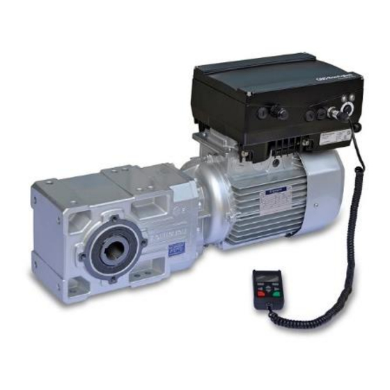
Speed regulator overview 2.3 Description of the DGM speed regulator The DGM speed regulator is a device for regulating the speed of three-phase AC motors. The speed regulator can be used as an element integrated in the motor (with an adapter plate) or near the motor (with an adapter plate for wall installation). -
Page 26: Installation
Resolution between 6 and 10 times In The network cable section must be provided based on the type of installation and the maximum permitted current. The protection of the network line must be guaranteed by the technician responsible for start-up. User instructions. DGM speed regulator... -
Page 27: Installation Requirements
- Size D (4 x M6 x 28) 4 Nm. POSSIBLE MATERIAL DAMAGE Failure to observe the warning could cause damage to the speed regulator! When installing a cover with an integrated foil keypad, make sure that the flat cable does not remain stuck. User instructions. DGM speed regulator... -
Page 28: Suitable Place Of Installation For The Speed Regulator Integrated On The Motor
Installation In the standard variant, the DGM is supplied in RAL 9005 (black). If the printed circuit boards are deinstalled (also in order to paint or cover the parts of the housing), the right to the warranty is voided! The tightening points and the seal surfaces must be kept free of paint for reasons of EMC and ground connection! 3.3.2... -
Page 29: Fundamental Connection Variants
Installation 3.3.3 Fundamental connection variants Fig. 9: Star or delta connection for the speed regulator integrated on the motor User instructions. DGM speed regulator... - Page 30 Fatal or serious injuries! Disconnect the electrical voltage from the speed regulator and secure it to prevent it from being reconnected. IMPORTANT INFORMATION Check regularly that the nuts are well tightened in their seat (1)! User instructions. DGM speed regulator...
- Page 31 Fatal or serious injuries! Disconnect the electrical voltage from the speed regulator and secure it to prevent it from being reconnected. IMPORTANT INFORMATION Check regularly that the nuts are well tightened in their seat (1)! User instructions. DGM speed regulator...
-
Page 32: Protection Against Short Circuits And Ground Leakage
The protection of the network line must be guaranteed by the technician responsible for start-up. 3.3.4 Protection against short circuits and ground leakage The speed regulator has internal protection against short circuits and ground leakage. User instructions. DGM speed regulator... -
Page 33: Wiring Instructions
0.75 to 1.5 mm², thin wire, from AWG 18 to AWG 14 Connection section: from 0.5 to 1.0 mm², thin wire (terminal tips with or without plastic neck) Stripping length: from 9 to 10 mm User instructions. DGM speed regulator... - Page 34 Pow er connections (sizes A - C) Sizes A - C The connection terminal boards for the network cable are located inside the speed regulator. Optionally, the DGM is equipped with terminals for connection to a brake chopper. The assignment can differ depending on the version.
- Page 35 Pow er connections (size D) Size D The connection terminal boards for the network cable are located inside the speed regulator. Optionally, the DGM is equipped with terminals for connection to a brake chopper. The assignment can differ depending on the version.
-
Page 36: Exclusion Of Electromagnetic Disturbances
Mechanical installation of sizes A - C Proceed as follows for the mechanical installation of the speed regulator: Open the series connection box for the motor. Disconnect the connection terminal board cables. Note the connection sequence. User instructions. DGM speed regulator... - Page 37 The standard adapter plate is an adapter plate whose lower part is not machined; that is holes were not made. If the DGM is ordered together with the gear motor, the adapter plate will be machined and installed by Bonfiglioli.
- Page 38 The technician responsible for start-up is responsible for observing the protection class for the seal of the adapter plate on the motor. In the case of questions, contact your contact persons at Bonfiglioli. Apply the gasket (3). Pass the motor connection cable to the connection terminal board through the adapter plate (1) and fasten it with the four fastening screws (4) and the four elastic motor elements (tightening torque: 2.0 Nm).
- Page 39 During installation of the motor cables, make sure that all of the terminal board bolts have the supplied nuts applied, even if the star point is not connected! Fig. 11: Jumper If present, wire the motor’s PTC/Klixon connection cable to terminals T1 and T2 (1) (tightening torque: 0.6 Nm). User instructions. DGM speed regulator...
- Page 40 Otherwise, this can cause fatal or serious injuries. Engage the speed regulator (3) in the adapter plate (4) and fasten it regularly with the four side screws (5) (sizes A – C) (torque: 4.0 Nm). User instructions. DGM speed regulator...
-
Page 41: Mechanical Installation Of Size D
Original terminal board (not included Holes in correspondence of the motor in the package) Gasket Optional long screw (for pos.7) Fastening screws with elastic elements Optional fastening screws with elastic elements O-ring DGM/support fastening screws Adapter plate/DGM support User instructions. DGM speed regulator... - Page 42 The standard adapter plate is an adapter plate whose lower part is not machined; that is holes were not made. If the DGM is ordered together with the gear motor, the adapter plate will be machined and installed by Bonfiglioli.
- Page 43 All contact points must be free of dirt and paint, otherwise a correct connection of the protective conductor is not guaranteed! Fasten the original terminal board (8) on the motor, using the optional terminal board extension (7) and the optional long screws (9) as an aid if necessary. User instructions. DGM speed regulator...
- Page 44 Connect the four cables (PE, U, V, W) with the relative section (depending on the power of the utilized DGM), to the original terminal board (8). IMPORTANT INFORMATION The connection cables (approx. 30 cm) needed for wiring the motor/DGM terminal board are not included in the package! INFORMATION...
- Page 45 Installation Pass the four cables (PE, U, V, W) through the DGM support. IMPORTANT INFORMATION Check that the O-ring (5) is well housed in its seat! 10. Carefully engage the speed regulator on the support (6) and fasten it uniformly with the two M8 screws (11) (torque: max.
- Page 46 If the motor has a temperature sensor, it must be connected to terminals T1 and T2 (1). For this purpose, remove the jumper inserted when initially supplied (2). If the jumper remains inserted, the motor temperature will not be monitored! User instructions. DGM speed regulator...
-
Page 47: Power Connection For Sizes A - C
Unscrew the four screws (1) on the housing cover (2) of the speed regulator and remove the cover. Pass the connection cable to the network through the cable gland (3). Connect the cables in the connection terminal board as follows: 230 V connection 400 V connection User instructions. DGM speed regulator... - Page 48 Table 3: Terminal assignment X1 - 3 x 400 Vac Terminal no. Name Assignment DC (+) 565 V network Not assigned DC (-) network Protective conductor Table 4: Terminal assignment X1 - DC power supply from 250 to 750 V User instructions. DGM speed regulator...
- Page 49 Table 5: Terminal assignment X1 - 1 x 230 Vac Terminal no. Name Assignment DC (+) 325 V network DC (-) network Protective conductor Table 6: Terminal assignment X1 - DC power supply from 120 to 350 V User instructions. DGM speed regulator...
-
Page 50: Power Connection Size D
The cable gland is used to lighten the traction; the PE connection cable must be connected in advance (significantly longer)! Connect the cables in the connection terminal board as follows: 400 V connection The protective conductor must be connected to the "PE” contact. User instructions. DGM speed regulator... - Page 51 If connecting a brake chopper to an optional brake resistor, use shielded cables with double insulation! Terminal no. Name Assignment Network phase 1 Network phase 2 Network phase 3 Protective conductor Table 7: Terminal assignment X1 - 3 x 400 Vac User instructions. DGM speed regulator...
- Page 52 Table 8: Terminal assignment X1 - DC power supply from 250 to 750 V Terminal no. Name Assignment Protective conductor Motor phase 1 Motor phase 2 Motor phase 3 Table 9: Motor connection assignment X4 User instructions. DGM speed regulator...
-
Page 53: Brake Chopper Connections
Brake chopper connection (-) Table 10 Assignment of the optional brake chopper terminals 3.4.6 Control connections X5, X6, X7 Control connec tions for th e stand ard application board Fig. 16: Control connections for the standard application board User instructions. DGM speed regulator... - Page 54 Connect the cover on the speed regulator housing and tighten it with the following torque: Size Tightening torque A - C 2 Nm (4 x M4 x 28) 4 Nm (4 x M6 x 28) User instructions. DGM speed regulator...
- Page 55 A. In 1 Actual PID value (parameter 3.060) A GND (Ground 10 V Ground A. In 2 free (not assigned) A GND (Ground 10 V) Ground Table 11: Terminal assignments X5 of the standard application board User instructions. DGM speed regulator...
- Page 56 Internal power supply voltage Reference value enabling (parameter Dig. In 1 1.131) Dig. In 2 free (not assigned) Dig. In 3 free (not assigned) Dig. In 4 Error reset (parameter 1.180) En-HW (enabling) Hardware enabling User instructions. DGM speed regulator...
- Page 57 Name Assignment Central contact relay 1 Closing contact relay 1 Opening contact relay 1 Table 12: Terminal assignment X6 (relay1) INFORMATION In the factory settings, relay 1 is programmed as the “error relay” (parameter 4.190). User instructions. DGM speed regulator...
- Page 58 Terminal no. Name Assignment Central contact relay 2 Closing contact relay 2 Opening contact relay 2 Table 13: Terminal assignment X7 (relay2) INFORMATION In the factory settings, “no function” is assigned to relay 2 (parameter 4.210). User instructions. DGM speed regulator...
- Page 59 A GND (Ground 10 V) Ground Dig. Out Error message (parameter 4.150) 10 V Out For external 24 V Out Internal power supply voltage 24 V Out Internal power supply voltage En-HW (enabling) Hardware enabling GND (Ground) Ground User instructions. DGM speed regulator...
-
Page 60: Connection Diagram
Connection diagram Fig. 18: Control connections Abbreviation Explanation Speed regulator type: DGM (3 x 400 Vac) Connection for external brake chopper (optional) M6 – Ground connection crew (connection for fault currents> 3.5 mA) RS485 programming interface (connector M12) Internal potentiometer... -
Page 61: Wall-Mounted Installation Of The Speed Regulator
3.5 Wall-mounted installation of the speed regulator 3.5.1 Location suitable for the wall-mounted installation Make sure that the location for the wall-mounted installation of a DGM satisfies the following conditions: The speed regulator must be mounted on a flat, stable surface. -
Page 62: Mechanical Installation Sizes A - C
Use the appropriate EMC screw connections to connect the shielded motor cable to the motor connection box,! Make sure that the shielding contact is implemented properly (large surface area)! Connect the prescribed PE connection in the motor connection box! Close the motor connection box. User instructions. DGM speed regulator... - Page 63 To obtain optimal convection for the speed regulator, pay attention during installation to the position of the screw connection (EMC) (5): it must face upward. Only vertical installation is permitted if the DGM does not have supplementary ventilation. User instructions. DGM speed regulator...
- Page 64 Reinsert the terminal board (2) in the adapter plate (3). Fix the terminal board (2) with the screw (1) (torque: 1.2 Nm). INFORMATION After fastening the terminal board (2), makes sure that it is supported in floating mode. User instructions. DGM speed regulator...
- Page 65 HAZARD Risk of fatal injury due to moving mechanical components! Fatal or serious injuries! After connecting the DGM, the motor has potential energy. Therefore, the connection must be made using a separate line, with insulation suitable for the motor cable! Only PTCs for motors that comply with DIN 44081/44082 can be connected! The speed regulator must be connected to the ground with the motor.
- Page 66 Place the speed regulator (9) on the adapter plate (3) such that the adapter neck enters in the opening at the base of the heat dissipator. Fasten the speed regulator (9) using the provided screws (10) on the adapter plate (3) (torque: 4.0 Nm). User instructions. DGM speed regulator...
-
Page 67: Mechanical Installation Size D
Use the appropriate EMC screw connections to connect the shielded motor cable to the motor connection box,! Make sure that the shielding contact is implemented properly (large surface area)! Connect the prescribed PE connection in the motor connection box! Close the motor connection box. User instructions. DGM speed regulator... - Page 68 Identify a position that complies with the required ambient conditions described in the chapter "Installation requirements". Mount the adapter plate (1) with four screws* on the wall. * The screws are not included in the scope of delivery. User instructions. DGM speed regulator...
- Page 69 For this purpose, use the fastening screws (5) included in the scope of delivery with the spring elements (4) (torque 8.5 Nm). IMPORTANT INFORMATION Check that the gasket (2) is well housed in its seat! User instructions. DGM speed regulator...
- Page 70 Set the o-ring (6) in the groove of the support (3). IMPORTANT INFORMATION Check that the O-ring (6) is well housed in its seat! Unscrew the four screws (7) from the cover (8) of the speed regulator (9). Remove the cover (8). User instructions. DGM speed regulator...
- Page 71 Fig. 28: Fastening the speed regulator on the size D support 10. Carefully insert the speed regulator (9) on the support (3). 11. Tighten the two parts evenly with the two M8 screws (10) (torque: max. 25,0 Nm). User instructions. DGM speed regulator...
- Page 72 The cable gland is used to lighten the traction; the PE connection cable must be connected in advance (significantly longer)! 13. Connect the cables in the connection terminal board [X1] (13) as follows: 400 V connection The protective conductor must be connected to the "PE” contact. User instructions. DGM speed regulator...
- Page 73 Table 14: Terminal assignment X1 - 3~ 400 V Terminal no. Name Assignment DC (+) (565 V) network Not assigned DC (-) network Protective conductor Table 15: Terminal assignment X1 - DC power supply from 250 to 750 V User instructions. DGM speed regulator...
- Page 74 (significantly longer)! 15. Connect the cables in the connection terminal boards [X4] (16) as follows: Terminal no. Name Assignment Protective conductor Motor phase 1 Motor phase 2 Motor phase 3 Table 16: Motor connection assignment X4 User instructions. DGM speed regulator...
-
Page 75: Power Connection
17. Tighten the two parts with the four screws (7) (torque 4 Nm). 3.5.4 Power connection The power connections are made as described in the chapter " generic motor Installation of the speed regulator integrated on a generic". User instructions. DGM speed regulator... -
Page 76: Brake Chopper Connections
Installation of the speed regulator integrated on a generic". 3.6 Deinstalling and installing the DGM fan size “D” The following section describes the replacement of the fan in the DGM size "D". For safety reasons, closely observe the safety instructions and information. HAZARD... -
Page 77: Deinstalling The Fan
Risk of electric shock and electric discharge. After shut-off, wait two minutes (time for capacitor discharge) Fig. 32: Fan deinstallation size D Unscrew the four screws (1) from the cover (2) of the speed regulator. Remove the cover (2) of the speed regulator. User instructions. DGM speed regulator... - Page 78 (4) "Brake chopper [X2] (optional)", (5) "Motor terminal [X4]", (6) "PTC/Klixon motor [X11]". Unscrew both screws (7). Carefully lift the speed regulator up off the support (8) and place it on a clean, flat surface. User instructions. DGM speed regulator...
-
Page 79: Installing The Fan
Installing the fan Insert the M12 connector (12) for the new fan unit (11) in the speed regulator connector. Insert the new fan unit (11) in the speed regulator and tighten the screws (9) and (10). User instructions. DGM speed regulator... - Page 80 Connect all the cables to the following connections: (3) "Network terminal [X1]" (see chapter "Power connection/size D") (4) "Brake chopper [X2] (optional)" (5) "Network terminal [X4]" (see chapter "Power connection/size D") (6) "PTC/Klixon motor [X11]” (optional) User instructions. DGM speed regulator...
- Page 81 Installation Place the cover (1) on the speed regulator housing. Tighten the two parts with the four screws (2) (torque: 4 Nm). User instructions. DGM speed regulator...
-
Page 82: Start-Up
Use suitable fuses with the relative current values between the network and the speed regular (see the technical data). The speed regulator must be ground connected together with the motor, as required. Otherwise, serious injuries may occur. User instructions. DGM speed regulator... -
Page 83: Communication
The speed regulator can be started up as follows: via the VPlus Dec software Fig. 34: PC software - start-up mask via the hand-held MMI control device* Fig. 35: Hand-held MMI control device * Man machine interface User instructions. DGM speed regulator... - Page 84 Start -up via the MMI* integrated in the cover (optional) Fig. 36: MMI option * Man machine interface User instructions. DGM speed regulator...
-
Page 85: Block Diagram
Analogue input 2 Fieldbus Autostart 1.131 Low/High- Revers Speed Motor current limit Ramps speed direction Reference Motor X(-1) speed control 1.020 1.021 5.070 5.071 1.051 1.050 1.150 1.053 1.052 Fig. 37: General generation structure of reference values User instructions. DGM speed regulator... -
Page 86: Steps For Start-Up
Install the VPlus Dec software (the programming software is supplied free of charge by BONFIGLIOLI. Required operating system Windows XP, Windows 7 or Windows 10 [32 / 64 Bit]). It is recommended to carry out the installation procedure as the administrator. -
Page 87: Start-Up Via The Pc, Combined With The Optional Mmi
Install the Vplus Dec software (the programming software is supplied free of charge by Bonfiglioli. Required operating system Windows XP, Windows 7 or Windows 10 [32 / 64 Bit]). It is recommended to carry out the installation procedure as the administrator. - Page 88 180° displa y ro tation Depending on the DGM installation position in the system, it may be necessary to rotate the display 180°. With the parameter 5.200 it is possible to rotate the display 180°.
-
Page 89: Parameters
Failure to observe can cause death, serious physical injuries or considerable material damage! Certain parameter settings or the change to parameter settings during operation can cause the DGM speed regulator to restart automatically after a period without the power supply voltage, or undesired changes can take place in operational behavior. INFORMATION If parameters are changed during operation, a few seconds may pass before a visual effect can be detected. -
Page 90: General Aspects Concerning The Parameters
(3.050), integral I (3.051) and derivative D (3.052) gain factors. If there are uncontrollable regulation differences, to prevent an infinite increase of the integral part, it is limited by a certain set value (corresponding to the "maximum frequency” (1.021)). User instructions. DGM speed regulator... - Page 91 This means, the reference value to indicate is 30 %. PID process controller operating mode 3.070 3.071 stand-by function Limitation Part-I 3.050 Frequency Reference y imax reference mode channel 1.130 Inverted feedback 3.061 3.052 3.060 Fig. 38: PID process regulation User instructions. DGM speed regulator...
- Page 92 “PID standby time” (3.070) at the "minimum frequency" (1.020). As the actual value deviates from the reference value for the set % value, the «PID standby hysteresis» (3.071), regulation (the motor) is restarted. Fig. 39: PID process regulation standby function User instructions. DGM speed regulator...
- Page 93 Fixed frequency 5 40 Hz from 2.051 to 2.057 from Fixed frequency 6 45 Hz from 2.051 to 2.057 from Fixed frequency 7 50 Hz from 2.051 to 2.057 Table 17: Fixed frequency logic table User instructions. DGM speed regulator...
-
Page 94: Structure Of The Parameter Tables
Acquisition status Other parameters correlated 0 = turn the speed regulator off and on to this parameter. for acquisition 1 = at speed 0 2 = during operation Value range (from – to – factory setting) User instructions. DGM speed regulator... -
Page 95: Applicable Parameters
Braking time 1 is the time the speed regulator requires to brake from the maximum frequency (1.021) to 0 Hz. If the set braking time cannot be observed, the quickest possible braking time is implemented. User instructions. DGM speed regulator... - Page 96 Acceleration time 2 is the time the speed regulator needs to accelerate from 0 Hz to the maximum frequency. The acceleration time can be extended by certain circumstances, such as the overload of the speed regulator. User instructions. DGM speed regulator...
- Page 97 The quick stop parameter is the time the inverter needs to brake from the maximum frequency (1.021) to 0 Hz. If the quick stop time cannot be observed, the quickest possible braking time is implemented. The quick stop is activated when the value of DIG.IN.5 is 0V. User instructions. DGM speed regulator...
- Page 98 1 = PID process regulator, based on the PID regulator reference value (3.050 – 3.071), 2 = fixed frequencies, according to the frequencies defined in parameters 2.051 – 2.057 3 = selection via DGM Soft-PLC 1,130 Setpoint of reference Unit: whole...
- Page 99 11 = Fixed frequency inputs (all the inputs that were selected in parameter 2.050) 12 = Internal potentiometer 13 = Foil keypad (Start and Stop keys) 14 = MMI/PC 15 = Virtual output (4.230) 16 = Integrated foil keypad User instructions. DGM speed regulator...
- Page 100 5 = Digital input 4 (function active with high signal) 6 = DGM Soft-PLC 7 = Analog input 1 (must be selected in parameter 4.030) 8 = Analog input 2 (must be selected in parameter 4.060) User instructions. DGM speed regulator...
- Page 101 14 = Integrated foil keypad: direction of rotation inversion key (only when operating) 15 = Integrated foil keypad: key I + II 16 = Integrated foil keypad: key I + II (only with the motor stopped) User instructions. DGM speed regulator...
- Page 102 In addition to the reset function (1.180), it is possible to select an automatic reset of the errors. = no automatic confirmation > 0 = time for the automatic reset of the error in seconds User instructions. DGM speed regulator...
- Page 103 In the example, 8 “automatic resets" were accepted. If an error occurs within 160 sec., at the 9th reset attempt "Error 22” occurs. This error must be confirmed manually, by turning off the inverter power supply. User instructions. DGM speed regulator...
-
Page 104: Fixed Frequency
P. xy 1,020 Def.: 1,021 Frequencies that must be set based on the connection model for digital inputs 1,100 1– 3 set in parameter 2.050. 1,150 See the chapter Explanation of the operating modes/fixed frequency. 2,050 User instructions. DGM speed regulator... -
Page 105: Motor Potentiometer Function
5 = Digital input 3 + / digital input 4 - 6 = Analog input 1 + / analog input 2 - (must be selected in parameter 4.030 / 4.050) 7 = DGM Soft- PLC 8 = Foil keypad (key I - / key II +) 2,151... - Page 106 Acquisition status: value (enter!) min.: the parameter: manual: max.: P. xy Def.: Determines if the reference value of the motor potentiometer remains even after the network current is absent. 0 = deactivated 1 = activated User instructions. DGM speed regulator...
-
Page 107: Pid Process Regulator
Unit: whole Relation with Parameter Acquisition status: min.: value (enter!) the parameter: manual: max.: Def.: Here it is possible to switch to PID mode: 0: Standard (without considering the actual frequency) 1: considering the actual frequency User instructions. DGM speed regulator... - Page 108 1,130 Def.: 3,069 PID fixed reference values that must be output based on the connection model to the digital inputs 1 – 3 set in parameter 3.069 (the selection must be made in parameter 1.130). User instructions. DGM speed regulator...
- Page 109 P. xy 3,060 Def.: Wakeup condition for the PID regulator from the standby function. When the regulation difference is greater than the value set in %, regulation restarts; see also the PID regulator operating modes. User instructions. DGM speed regulator...
- Page 110 P. xy Def.: If after this set time the actual PID value did not reach at least 5% and the speed regulator is at its maximum limit, the DGM switches to the PID dry cycle with error no. 16. 3,073...
- Page 111 Minimum PID frequency 3.080 2 = 20 Hz Minimum frequency for PID reference value 0 % = 10 Hz Minimum frequency for PID reference value 50 % = 15 Hz Minimum frequency for PID reference value 100 % = 20 Hz User instructions. DGM speed regulator...
-
Page 112: Analog Inputs
P. xy Def.: Defines the maximum value of the analog inputs as a percentage of the interval. Example: 0…10 V or 0…20 mA = 0 %...100 % 2…10 V or 4…20 mA = 20 %...100 % User instructions. DGM speed regulator... - Page 113 4,030 / 4,060 Alx function Unit: whole Relation with Parameter Acquisition status: value (enter!) min.: the parameter: manual: max.: P. xy Def.: Function of the analog inputs 1/2 0 = Analog input 1 = Digital input User instructions. DGM speed regulator...
- Page 114 Relation with Parameter Acquisition min.: - 10000 value (enter!) the parameter: manual: status: max.:+ 10000 P. xy 4,033 / 4,063 Def.: 4,034 / 4,064 Selection of the upper limit of a physical quantity to display. User instructions. DGM speed regulator...
-
Page 115: Digital Inputs
DIx inversion Unit: whole 4.113 Relation with Parameter Acquisition status: min.: value (enter!) the parameter: manual: max.: P. xy Def.: With this parameter, it is possible invert the digital input. 0 = inactive 1 = active User instructions. DGM speed regulator... -
Page 116: Analogue Output
4,102 Selection of the process value output on the analog output. Depending on the selected process value, the min. and max. values must be adapted (4.101 / 4.102). not assigned / DGM Soft-PLC Intermediate circuit voltage Network voltage Motor voltage... -
Page 117: Digital Outputs
P. xy 4,151 / 4,171 Def.: 4,152 / 4,172 Selection of the process quantity on which the output must be switched. not assigned / DGM Soft-PLC Intermediate circuit voltage Network voltage Motor voltage Motor current Actual frequency value IGBT temperature... - Page 118 Actual PID value Actual frequency value Absolute torque value Absolute frequency reference value after ramp Absolute frequency reference value Instantaneous absolute number of revs value Active motor current limit Technical-actual comparison (Para. 6.070 – 6.071) User instructions. DGM speed regulator...
-
Page 119: Relay
P. xy 4,191 / 4,211 Def.: 4,192 / 4,212 Selection of the process quantity on which the output must be switched. not assigned / DGM Soft-PLC Intermediate circuit voltage Network voltage Motor voltage Motor current Actual frequency value IGBT temperature... - Page 120 Actual PID value Actual frequency value Absolute torque value Absolute frequency reference value after ramp Absolute frequency reference value Instantaneous absolute number of revs value Active motor current limit Technical-actual comparison (Para. 6.070 – 6.071) User instructions. DGM speed regulator...
- Page 121 Indicates the duration of the activation delay. 4.194/ 4.214 Relay x-Off delay Unit: Relation with Parameter Acquisition status: min.: value (enter!) the parameter: manual: max.: 10000 P. xy 4,193 / 4,213 Def.: Indicates the duration of the deactivation delay. User instructions. DGM speed regulator...
-
Page 122: Virtual Output
P. xy Def.: 1,054 Selection of the process quantity on which the output must be switched. 1,131 1,150 not assigned / DGM Soft-PLC 4,231 Intermediate circuit voltage 4,232 Network voltage 5,010 / 5,011 Motor voltage 5,090 Motor current... - Page 123 Unit: Relation with Parameter Acquisition status: min.: - 32767 value (enter!) the parameter: manual: max.: 32767 P. xy 4,230 Def.: If the set process quantity exceeds the activation limit, the output is set to 1. User instructions. DGM speed regulator...
- Page 124 Indicates the duration of the activation delay. 4,234 VO Off delay Unit: Relation with Parameter Acquisition status: value (enter!) min.: the parameter: manual: max.: 10000 4,233 P. xy Def.: Indicates the duration of the deactivation delay. User instructions. DGM speed regulator...
-
Page 125: External Error 1/2
P. xy 4,110 / 4,113 Def.: 4,230 Selection of the source via which an external error can be communicated. not assigned / DGM Soft-PLC Digital input 1 Digital input 2 Digital input 3 Digital input 4 Virtual output (parameter 4.230) Analog input 1 (must be selected in parameter 4.030) - Page 126 Acquisition status: min.: value (enter!) the parameter: manual: max.: 1000 P. xy 33,034 Def.: A reduction factor can be set here. The indication of the number of mechanical revs can be adapted using the reduction factor. User instructions. DGM speed regulator...
-
Page 127: Block Detection
30 seconds (if nominal frequency is < 10%, the error is not generated). If the acceleration time is > 30 seconds, instead of 30 seconds, half of the acceleration ramp time is considered. 0 = function deactivated 1 = function active User instructions. DGM speed regulator... - Page 128 Foil keypad: key I for saving data set 1, key II for saving data set 2 The 2nd data set is displayed in the PC software only if this parameter is <> 0. The MMI always displays the values of the currently selected data set. User instructions. DGM speed regulator...
- Page 129 9999 P. xy Def.: A password for accessing the expert mode on the MMI can be assigned here. 0: Password request deactivated The password can be set individually in both data sets. User instructions. DGM speed regulator...
-
Page 130: Fieldbus
In order for this address to be used, the device address coding switches must be set to 00. The change to the fieldbus address is only acquired after the DGM is restarted. The Profibus devices are set automatically to the address "Default 125" with the coding switch positioned to the address "00"... - Page 131 P. xy Def.: Bus timeout, if a fieldbus telegram is not received when the set time expires, the DGM deactivates itself, signaling the error “bus timeout". The function is only activated after a telegram is received. 0 = control deactivated...
-
Page 132: Power Parameters
Also the type of regulation must be selected as a result (parameter 34.010). 33,015 Optimization R Unit: % Relation with Parameter Acquisition status: min.: value (enter!) the parameter: manual: max.: P. xy Def.: If necessary, this parameter can be used to optimize the start-up behavior. User instructions. DGM speed regulator... - Page 133 Motor power Unit: W Relation with Parameter Acquisition status: min.: value (enter!) the parameter: manual: max.: 55000 P. xy Def.: A power value [W] P must be set here that corresponds to the nominal motor power. User instructions. DGM speed regulator...
- Page 134 Parameter Acquisition status: min.: value (enter!) the parameter: manual: max.: P. xy Def.: Only for asynchronous motors. Here the dispersion inductance can be optimized if the value detected automatically (during motor identification) is not sufficient. User instructions. DGM speed regulator...
- Page 135 Acquisition status: min.: value (enter!) the parameter: manual: max.: P. xy Def.: Only for synchronous motors. (Not available) Here the stator inductance can be optimized if the value detected automatically (during motor identification) is not sufficient. User instructions. DGM speed regulator...
-
Page 136: Control I T
For thermally sensitive applications, we recommend using contacts that protect the windings! 33,011 Time I Unit: s Relation with Parameter Acquisition status: min.: value (enter!) the parameter: manual: max.: 1200 P. xy 33,010 Def.: Time after which the speed regulator deactivates with I User instructions. DGM speed regulator... -
Page 137: Switching Frequency
Unit: whole Relation with Parameter Acquisition status: min.: value (enter!) the parameter: manual: max.: P. xy 33,001 Def.: 34,011 Selection of the regulation type: 100 = open-loop asynchronous motor 200 = open-loop synchronous motor (not available) User instructions. DGM speed regulator... - Page 138 Here the amplification of the control of the number of regulator revs can be optimized if the results detected automatically (during motor identification) are not sufficient. For synchronous motors: (Not available) The amplification of the control of the number of regulator revs can be set here. User instructions. DGM speed regulator...
- Page 139 Motor at rated point 0 = 1410 rpm 1 = 1500 rpm 50 Hz is always displayed as the actual frequency. Deactivating slip compensation may cause the block detection to no longer function in a reliable manner. User instructions. DGM speed regulator...
-
Page 140: Quadratic Characteristic Curve
P. xy 34,120 Def.: Only for asynchronous motors. The percentage at which the flow must be decreased can be set here. In case of excessive variations during operation, deactivation may take place due to overvoltage. User instructions. DGM speed regulator... -
Page 141: Brake Chopper
0: deactivated 1: active 5.4.7 Protection functions 36,020 Network monitoring deactivated Unit: Integer Relation with Parameter Acquisition status: value (enter!) min.: the parameter: manual: max.: Def.: Network monitoring can be deactivated here. 0: deactivated 1: active User instructions. DGM speed regulator... -
Page 142: Troubleshooting
Disconnect the electrical voltage from the device and secure it to prevent it from being reconnected. Only replace damaged parts or components with original spare parts. Risk of electric shock and electric discharge. After shut-off, wait two minutes (time for capacitor discharge) User instructions. DGM speed regulator... -
Page 143: Presentation Of The Led Flashing Codes For Error Detection
Ready to start operating (activate En_HW for operation) Operation / ready Warning Error Motor data identification Initialization Firmware update Bus operating error Bus ready to start operating error Table 18: Flashing LED codes LED off LED on LED flashing LED flashing quickly User instructions. DGM speed regulator... -
Page 144: List Of Errors And System Errors
Check the PLC client suitable for the device version number and the firmware device firmware Application <> power Internal communication Electromagnetic communication problems between the compatibility disturbances application’s printed circuit (EMC) board and the one for the power User instructions. DGM speed regulator... - Page 145 Check the motor or does not function correctly. connections/motor and 5,082 regulator parameters; deactivate the error if necessary (5.082). CF application Excessive internal Cooling insufficient, low overheating temperature number of revs and high torque, excessive pulse frequency. User instructions. DGM speed regulator...
- Page 146 External error 2 Eliminate the external error is active. 5,011 Motor detection Motor identification error Check the DGM / motor and the PC / MMI / DGM connections / restart of motor identification STO input plausibility The states of the two...
- Page 147 / reduce the ambient temperature / check the fan Motor protection switch The internal protection I T for Permanent overload the motor tripped (parameterizable) Ground leakage Ground leakage of a motor Isolation fault phase User instructions. DGM speed regulator...
- Page 148 1 -3 Permitted resets = Wait time s 4 -5 Permitted resets = Wait time s > 5 Permitted resets = Wait time s The number of resets performed is deleted after 120 s without errors! User instructions. DGM speed regulator...
-
Page 149: Deinstallation And Disposal
Dispose of the speed regulator, packaging and the replaced components in accordance with the provisions of the country where the speed regulator is installed. The speed regulator must not be disposed of with normal household waste. User instructions. DGM speed regulator... -
Page 150: Technical Data
Recommended motor power (4-pole asynchronous motor) with network voltage equal to 400 VAC. Vibration test combined with degree of precision 2 according to FN942017, part 4. For the observance of the overvoltage category < 3 s may cause network interruption/intermediate circuit undervoltage User instructions. DGM speed regulator... -
Page 151: General Technical Data For 230 V Devices
230 V device technical data (subject to technical changes) Recommended motor power (4-pole asynchronous motor) with network voltage equal to 230 VAC. Vibration test combined with degree of precision 2 according to FN942017, part 4. User instructions. DGM speed regulator... -
Page 152: Interface Specification
24 V Supply voltage 10 V Auxiliary voltage U = 10 V DC Short circuit resistance Imax = 30 mA Table 20: Interface specification * according to standard UL 508C max. 2 A are permitted! User instructions. DGM speed regulator... -
Page 153: Derating Of The Output Power
IGBT temperature of 95°C is exceeded or with a permitted internal temperature of 85°C, the speed regulator turns off. With the exception of the 22 kW regulator (size D 130%), all DGM type speed regulators are designed for an overload of 150% for 60 sec (every 10 min). - Page 154 Ambient temperature [°C] Umgebungstemperatur [°C] Fig. 42: Power derating for wall-mounted speed regulators (sizes A – C) 110% 100% Umgebungstemperatur [°C] Ambient temperature [°C] Fig. 43: Power derating for wall-mounted speed regulators (size D with fan) User instructions. DGM speed regulator...
-
Page 155: Power Derating Based On The Installation Altitude
In the range between 2000 m ≥ 4000 m overvoltage category 2 must be observed due to the low air pressure! To observe the overvoltage category: an external overvoltage protection must be used in the DGM power supply line (network cable). the input voltage must be reduced. -
Page 156: Power Derating Based On The Switching Frequency
The maximum output values can be determined based on the following characteristic curve. 120% 110% 100% Pulse frequency [kHz] Taktfrequenz [kHz] Fig. 46: Power derating of the maximum output current based on of the switching frequency User instructions. DGM speed regulator... -
Page 157: Accessories
9.1.1 Adapter plates for a generic motor A standard motor adapter plate is available for each DGM size (with an integrated terminal board for sizes A to C). The customer is responsible for making the four holes in the standard motor adapter plate. - Page 158 Accessorie s IMPORTANT INFORMATION Bonfiglioli shall not be held responsible for the connection between the motor and DGM! Fig. 47: Standard adapter plate drilling template size A Fig. 48: Standard adapter plate drilling template size B User instructions. DGM speed regulator...
- Page 159 Accessorie s Fig. 49: Standard adapter plate drilling template size C Fig. 50: Standard adapter plate drilling template size D User instructions. DGM speed regulator...
-
Page 160: Bonfiglioli Motor Adapter Plates
If using cylindrical head screws (see DIN 912 / DIN 6912) or flat head screws (see DIN EN ISO 7380), drill the drilling template on the DGM support frame, as per the relative drawings. The drilling centers must be located along the relative center lines of the slots shown in the diagrams. -
Page 161: Wall Adapter Plates (Standard)
9.1.3 Wall adapter plates (standard) A standard wall adapter plate is available for each DGM size (with an integrated terminal board for sizes A to C). There are already four holes for fastening the adapter plate and an EMC screw connection. - Page 162 Accessorie s Fig. 52: Standard wall adapter plate drilling template size B Fig. 53: Standard wall adapter plate drilling template size C User instructions. DGM speed regulator...
- Page 163 Accessorie s Fig. 54: Standard wall adapter plate drilling template size D User instructions. DGM speed regulator...
-
Page 164: Foil Keypad
Accessorie s 9.2 Foil keypad As an option, the devices of the DGM family are also available with an integrated foil keypad. This keypad makes it possible to have a complete control system for the speed regulator on the device. - Page 165 I and II integrated in the foil keypad (select on the foil keypad: key I to the right / key II to the left always). The direction of rotation can be inverted while the motor is operating, but also when it is stopped. The integrated LEDs display the instantaneous direction of rotation. User instructions. DGM speed regulator...
- Page 166 This function can be used to increase or decrease the reference value. The integrated LEDs display if the minimum and maximum reference values have been reached. To activate this function, the reference setpoint indication (parameter 1.130) must be set on the motor potentiometer! User instructions. DGM speed regulator...
- Page 167 This turns on during operation. Fault LED: This turns on when there is an error. It flashes as soon as an error can be reset. INFORMATION PC software is required in order to parameterize these functions. User instructions. DGM speed regulator...
-
Page 168: Hand-Held Mmi Control Device Incl. 3 M Of Rj9 Connection Cable To The M12 Connector
9.4 PC USB communication cable on the M12/RS485 connector (integrated converter) As an alternative to the hand-held MMI control device, a DGM can be operated also using the PC communication cable and the VPlus Dec software. User instructions. DGM speed regulator... -
Page 169: Authorizations, Standards And Directives
The PTC connection cable may not exceed 5 m, otherwise the factory jumper must remain inserted. The following is recommended for monitoring the motor temperature: • The integrated function I • The use of an external PTC assessment device that can be processed via the DGM. User instructions. DGM speed regulator... -
Page 170: Classification Based On Iec/En 61800-3
Industrial environment with its own power supply network that is separated from the low voltage public network by a transformer. 10.3 Standards and directives The following apply in particular: Electromagnetic Compatibility directive (directive 2014/30/EU) Low Voltage directive (directive 2014/35/EU) User instructions. DGM speed regulator... -
Page 171: Quick Start-Up
Quick sta rt -up 11. Quick start-up 11.1 Quick start-up of the asynchronous motor Fig. 56: Block diagram for the quick start-up of the asynchronous motor User instructions. DGM speed regulator... - Page 172 Notes User instructions. DGM speed regulator...
- Page 173 Bonfiglioli Riduttori S.p.A. Via Giovanni XXIII, 7/A 40012 Lippo di Calderara di Reno Bologna, Italy Tel. +39 051 647 3111 Fax +39 051 647 3126 bonfiglioli@bonfiglioli.com www.bonfiglioli.com User instructions. DGM speed regulator...
Need help?
Do you have a question about the DGM and is the answer not in the manual?
Questions and answers