
Related Manuals for Dream Chip ATOM one SSM500


Summary of Contents for Dream Chip ATOM one SSM500
- Page 1 Operational Manual Dream Chip Technologies ATOM one SSM500 Super Slow-Motion Camera System www.atom-one.de info@atom-one.de https://gitlab.com/dreamchip/provideo-downloads/...
-
Page 2: Table Of Contents
Content Table of Content Introduction ......................4 Quality Policy ....................5 Technical Data ......................6 Dimensions C-Mount ................... 6 Dimensions B4 ....................7 Overview ......................8 Sensor ......................8 Recoding Engine (Trigger Mode) ............... 8 Image Processing Features ................8 Video Output .................... - Page 3 Any of the trademarks, brand names or similar rights that are mentioned, used or cited in this document are the property of their respective owners. Dream Chip Technologies GmbH is neither endorsed by nor affiliated with any of the holders of any such rights.
-
Page 4: Introduction
ATOM one SSM500 system. More technical details about the camera functions can be found in the reference manual. The ATOM one SSM500 is the smallest 2/3” Full HD super slow-motion live camera with inbuild recording or quad SDI streaming. The ATOM one SSM500 camera family consists of multiple versions with different lens mount options. -
Page 5: Quality Policy
Introduction 1.1 Quality Policy Dream Chip Technologies GmbH is committed to the delivery of safe, effective and reliable products to their consumers, a fundamental element of our Company’s Targets. Our mission is to bridge the gap between demand and offer by supporting our customers with sophisticated technology, thus enabling them to launch new products without having to neglect their core business. -
Page 6: Technical Data
Technical Data 2 Technical Data All versions of the camera feature seven 1/4” x 5 mm tripod threads at the bottom for balanced mounting as well as several M3 x 5 mm threads on the top for lens drive mounts or other accessories. Depending on the lens mount, additional threads are available (see below). -
Page 7: Dimensions B4
Technical Data 2.2 Dimensions B4 At the front there are six additional 1/4” x 5 mm tripod threads for accessories (three on the top and three on the bottom). Please refer to the drawing below for details. www.atom-one.de info@atom-one.de https://gitlab.com/dreamchip/provideo-downloads/... -
Page 8: Overview
Technical Data 2.3 Overview Common attributes for all models: • Power supply: 11.5 V to 36 V, 25 W • Operation conditions: 0 °C to +50 °C • Active cooling Attributes that depend on the lens mount: Lens Mount Dimensions (WxHxL) Weight C-Mount 60mm x 60mm x 190mm... -
Page 9: Video Output
Autostart with last settings • Embedded time code • Tri-level sync (genlock) input and output • Remote control via RS485 and RS232 (3.3V) • Lens control o C-Mount: Dream Chip Lens control system o B4: Full control of B4 motors www.atom-one.de info@atom-one.de https://gitlab.com/dreamchip/provideo-downloads/... -
Page 10: Connectors
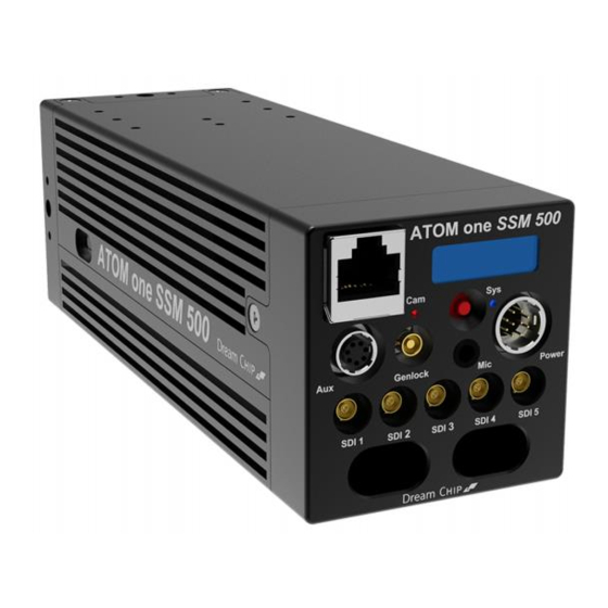
Connectors 3 Connectors The ATOM one SSM500 has 10 connectors at the back side. 3.1 Power / RS485 connector Dream Chip Technologies offers an optional Power / Control cable. www.atom-one.de info@atom-one.de https://gitlab.com/dreamchip/provideo-downloads/... - Page 11 Connectors For power and control, a Hirose male HR10A-10R-10PB connector is used. The following table shows the required plugs. Female Signal Power RS485 HR10A-10P- XLR 4-pin ITT Female 10S(73) male M-XL-3-11L 6-wire AWG 6-wire AWG 26 26 Power RS422 cable cable 6 + 7 + 10 Power in...
-
Page 12: Aux Connector
Connectors 3.2 Aux connector The AUX connector is a Hirose female HR10A-7R-6SB pin connector which can be used for lens control or local control via UART. The following table shows the required plug. Male Pin HR10A-7P-6P(73) Signal Power pass through Uart TX 3.3V Uart RX 3.3V Lens I2C SCL... -
Page 13: Microphone Input
The network connector is reserved for future applications like control via IP. 3.7 SD card slot The ATOM one SSM500 has a SD card slot on the right side. This slot is used for firmware updates. Details can be found in chapter 8. -
Page 14: Optical System
4 Optical System 4.1 C-Mount Back-Focus Adjustment The back-focus of the ATOM one SSM500 is adjustable. This helps to adapt to any lens to have a perfect focus. The following diagram is showing the components of the lens mount, from left to right those are: •... -
Page 15: B4 Back-Focus Adjustment
Optical System 4.2 B4 Back-Focus Adjustment The back-focus of the ATOM one SSM500 is adjustable. This helps to adapt to any lens to have a perfect focus. The following diagram is showing the optical converter, what can be removed for adjustment. -
Page 16: Power On/Off
Power On/Off 5 Power On/Off After connecting the power cable, the camera will turn on automatically and the Sys LED begins to blink green. The boot process takes about 20 seconds and is being visualized in the OLED display. During boot the fan will spin at maximum speed. -
Page 17: Display And Status Leds
Blue flashing Ready Device is up and waiting commands The ATOM one SSM500 has a build in OLED display which shows additional status information. This includes the current firmware version and the IP address. www.atom-one.de info@atom-one.de https://gitlab.com/dreamchip/provideo-downloads/... - Page 18 Display and Status Leds The OLED display will show the following screens, each screen is shown for 3 seconds before switching to the next screen: • Main Screen: Shows the operational mode (“TRIG” for the Trigger Mode and “SSM” for the SSM Mode), the firmware version and the IP address.
-
Page 19: Operation Modes
Reference Manual. 7.1 Trigger Mode In this variant the ATOM one SSM500 works as a stand alone camera with internal recording. It can record up to 500 frames per second with a memory depth of 30.000 frames. -
Page 20: Production Preparation
Operation modes Record 500 FPS / 1080p25 = 20x In addition to that, the playback speed can be slowed down to further increase the ratio. In trigger mode the camera has 2 independent output channels: • Live o Always shows the live stream o The live frame rate is independent of the recording frame rate o Is shown on SDI outputs 1 &... -
Page 21: Trigger Workflows
Operation modes 5. Select the color profile on the live channel e.g. 6500K (playback will follow automatically) 6. Setup white balance or use auto white balance 7. Start recording on a buffer 7.1.2 Trigger Workflows Since the SSM500 Trigger does have multiple independent image processing pipelines, the color workflow is different to other cameras. -
Page 22: Ssm Mode
Risk: Operator must make sure that settings get pulled, otherwise playback can have wrong look 7.2 SSM Mode In this mode the ATOM one SSM500 does not use its internal storage. The camera is steaming in super slow motion speed with up to 240 FPS. www.atom-one.de info@atom-one.de... - Page 23 Operation modes The slow motion ratio is changed by adjusting the number of active phases. There are 4 different phase settings possible: • 1 Phase: SDI 1 → 1x • 2 Phases: SDI 1, SDI 2 → 2x • 3 Phases: SDI 1, SDI 2, SDI 3 → 3x •...
-
Page 24: Firmware Update Via Sd Card
Firmware Update via SD Card 8 Firmware Update via SD Card The firmware can be updated via SD card. Make sure, that the power supply of the camera is in a stable state. A firmware update will reset all camera settings to their default values. You can download the latest updated from our GitLab repository: https://gitlab.com/dreamchip/provideo-downloads Procedure:... -
Page 25: Provideo Control Software
ProVideo camera control software gives an easy access to most of the camera functions. To use the software you need a serial connection from ATOM one SSM500 to a Windows PC. This can be done with a USB – RS485 adapter. You can build your own adapter with a serial FTDI cable or purchase a cable from Dream Chip. -
Page 26: Faq
115200 8N1. 10.2 Q: Is there a hardware camera controller available Currently, Dream Chip does not provide a hardware camera controller, but party controllers are available in the market. A free Windows software and a full API documentation comes with the camera. -
Page 27: Warranty
Dream Chip Technologies GmbH parts or supplies, or d) to service a product that has been modified or integrated with other products when the effect of such a modification or integration increases the time or difficulty of servicing the product. -
Page 28: Certifications
Certifications 12 Certifications 12.1 CE Compliance ATOM one SSM500 has been shown to comply with the listed technical standards below. The tests have been done according to the measurement procedures specified in European Council Directive- EMC Directive 2014/30/EU. The ATOM one SSM500 passed the tests performed according to: •...
Need help?
Do you have a question about the ATOM one SSM500 and is the answer not in the manual?
Questions and answers