Table of Contents
Advertisement
Quick Links
Advertisement
Table of Contents

Subscribe to Our Youtube Channel
Related Manuals for AgriMetal GR-400

Summary of Contents for AgriMetal GR-400
- Page 1 SELF-PROPELLED GREENS ROLLER MODEL GR-400 OPERATOR'S MANUAL...
- Page 2 This warranty shall not apply to any Greens Roller which has been altered outside the factory in any way so as, in the judgement of AgriMetal, to affect its operation or reliability, or which has been subject to misuse, neglect or accident.
- Page 3 Dealer’s Rep. Signature Signature The above equipment and Operator’s Manual have been received by me and I have been thoroughly instructed as to care, adjustments, safe operation and applicable warranty policy. Date Owner's Signature WHITE YELLOW PINK AGRIMETAL INC. DEALER CUSTOMER...
- Page 5 SERIAL NUMBER LOCATION Always give your dealer the serial number of your AgriMetal Self-Propelled Greens Roller when ordering parts or requesting service or other information. The serial number plate is located where indicated. Please mark the number in the space provided for easy reference.
-
Page 7: Table Of Contents
TABLE OF CONTENTS SECTION DESCRIPTION PAGE Introduction ............1 Safety ..............3 General Safety ............4 Equipment Safety Guidelines ........ 5 Safety Training ............6 Safety Signs ............6 Preparation ............7 Maintenance Safety ..........7 Operating Safety ............ 8 Transport Safety ............ -
Page 9: Introduction
This equipment has been designed and manufactured to meet the needs of a discerning turf care industry. Safe, efficient and trouble free operation of your AgriMetal Greens Roller requires that you and anyone else who will be operating or maintaining the machine, read and understand the Safety, Operation, Maintenance and Trouble Shooting information contained within the Operator's Manual. -
Page 11: Safety
If you have any questions not answered in this manual or require additional copies or the manual is dam- aged, please contact your dealer at AgriMetal Inc., 1006 Rue Principale, Wickham, Quebec, Canada, J0C 1S0. Phone (819) 398-6883 or fax (819) 398-5311. -
Page 12: General Safety
SAFETY 2.1 GENERAL SAFETY YOU are responsible for the SAFE operation and 1. Read and understand the Op- maintenance of your AgriMetal Self-Propelled erator’s Manual and all safety Greens Roller. YOU must ensure that you and signs before operating, main-... -
Page 13: Equipment Safety Guidelines
2.2 EQUIPMENT SAFETY GUIDELINES 1. Safety of the operator and bystanders is one of 7. Never exceed the limits of a piece of machinery. the main concerns in designing and developing If its ability to do a job, or to do so safely, is in question - DON'T TRY IT. -
Page 14: Safety Training
2.3 SAFETY TRAINING 2.4 SAFETY SIGNS 1. Safety is a primary concern in the design and 1. Keep safety signs clean and legible at all manufacture of our products. Unfortunately, our times. efforts to provide safe equipment can be wiped out by a single careless act of an operator or 2. -
Page 15: Preparation
2.5 PREPARATION 2.6 MAINTENANCE SAFETY 1. Good maintenance is your responsibility. Poor 1. Never operate the tractor and machine until you have read and completely understand this maintenance is an invitation to trouble. manual, the tow vehicle Operator's Manual, and 2. -
Page 16: Operating Safety
2.7 OPERATING SAFETY 1. Please remember it is important that you read 8. Read Operator's Manual before starting. Re- and heed the safety signs on the Self-Propelled view safety instructions annually. Greens Roller. Clean or replace all safety signs if they cannot be clearly read and understood. 9. -
Page 17: Transport Safety
2.8 TRANSPORT SAFETY 2.10 REFUELLING SAFETY 1. Handle fuel with care. It is highly flammable. 1. The machine is not designed or equipped to travel on public roads. Do not drive or transport 2. Allow engine to cool for 5 minutes before re- on public roads fuelling. -
Page 18: Gas Motor Safety
2.12 GAS MOTOR SAFETY 14. DO NOT crank engine with spark plug removed. If engine is flooded, place throttle in "FAST" position and crank until engine starts. BEFORE STARTING ENGINE, READ AND UNDERSTAND THE OPERATING AND MAIN- 15. DO NOT strike flywheel with a hard object or TENANCE INSTRUCTIONS THAT CAME WITH metal tool as this may cause flywheel to shatter YOUR ENGINE. -
Page 19: Sign-Off Form
2.13 SIGN-OFF FORM AgriMetal follows the general Safety Standards specified by the American Society of Agricultural and Biological Engineers (ASABE),the Occupational Safety and Health Administration (OSHA) and CE regulations. Anyone who will be operating and/or maintaining the Self-Propelled Greens Roller must read and clearly understand ALL Safety, Operating and Maintenance information presented in this manual. -
Page 21: Safety Sign Locations
3 SAFETY SIGN LOCATIONS The types of safety signs and locations on the equipment are shown in the illustrations that follow. Good safety requires that you familiarize yourself with the various safety signs, the type of warning and the area, or particular function related to that area, that requires your SAFETY AWARENESS. - Page 22 The types of safety signs and locations on the equipment are shown in the illustrations that follow. Good safety requires that you familiarize yourself with the various safety signs, the type of warning and the area, or particular function related to that area, that requires your SAFETY AWARENESS. •...
-
Page 23: Assembling
4 ASSEMBLING 4.1 MACHINE ASSEMBLY The machine is shipped from the factory in a partially disassembled configuration and at- tached to a pallet that provides for easy moving and handling. Always use tools, equipment and forklifts of appropriate size and capacity for the job. - Page 24 5. Remove hitch from pallet by removing screws securing it. Clevis Screw Pole Screw Fig. 2 HITCH 6. Remove anchor bolts from hitch mounting channel under trailer frame. Bolts 7. Remove hitch and bring to front of pallet. Removed Fig. 3 ANCHOR BOLTS...
- Page 25 8. Attach hitch to trailer with anchor bolts and tighten to their specifed torque. Fig. 4 ANCHOR BOLTS 9. Position hitch assembly: a. Install hitch. Hitch Installed b. Turn jack to extend wheel in the down direction. c. Lower wheel until it touches the ground.
- Page 26 10. Remove front frame anchor: a. Remove anchor screws. Anchor Screws b. Remove anchor bolt. Anchor Bolt c. Remove anchor frame. Frame Removed Fig. 6 FRAME ANCHOR...
- Page 27 11. Attach trailer to tow unit: a. Align hitch and clevis. Aligning b. Install drawbar pin and retainer. Drawbar Pin c. Connect safety chain. Safety Chain d. Retract jack and rotate 90° into its stowed position. Jack Stowed Fig. 7 HOOKING UP...
- Page 28 12. Drive trailer off the pallet. On Pallet Off Pallet Fig. 8 DRIVING FORWARD...
- Page 29 13. Connect battery: a. Remove anchor bolts from battery pole. Shipping b. Connect cable. Anchor Bolt c. Tighten anchor bolt to its specified torque. Connecting d. Move plastic shield over battery pole to cover cable connection. Cover Fig. 9 CONNECT BATTERY...
- Page 30 14. Install ignition key: a. Remove key from manual cannister. Manual Cannister b. Insert key into ignition switch. Ignition Switch Fig. 10 IGNITION KEY...
- Page 31 15. Lower trailer ramp: a. Cut plastic tie to rear support bracket. Rear Plastic Tie b. Release rear support bracket latch. Bracket Latch c. Cut plastic tie to front support bracket. Front Plastic Tie d. Release front support bracket. Bracket Released Fig.
- Page 32 16. Use the handle to lower the ramp to the ground. NOTE Do not unload machine unless trailer is attached securely to tow vehicle. Fig. 12 RAMP LOWERED...
- Page 33 17. Add gas to fuel tank: a. Raise seat assembly. Seat Assembly b. Remove gas cap. Gas Cap c. Add fuel to tank. d. Close fuel tank cap. Refueling e. Lower seat assembly into its operating configuration. Seat Assembly Lowered Fig.
- Page 34 18. Unload Greens Roller: a. Climb on seat. b. Start engine. NOTE Do not unload machine unless trailer is attached securely to tow vehicle. Starting Engine c. Drive machine down the ramp. • Starting Starting • Down STarting d. Off ramp. Down Ramp Fig.
- Page 35 19. Remove trailer frame shipping anchor bolt and stow. Fig. 15 SHIPPING ANCHOR BOLT...
-
Page 37: Operation
5.1 TO THE NEW OPERATOR OR OWNER Follow all safety instructions exactly. Safety is AgriMetal Self-Propelled Greens Rollers are de- everyone's business. By following recommend- signed to efficiently roll over a grass-covered sur- ed procedures, a safe working environment is face to keep it level and trim. -
Page 38: Machine Components
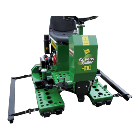
5.2 MACHINE COMPONENTS The AgriMetal Greens Roller is a self-propelled The steering wheel turns the right roller assembly to machine designed to roll over golf course greens to manoeuvre the machine where the operator wants keep them even for consistent putting. It is powered to go. -
Page 39: Break-In
5.3 BREAK-IN 5.4 PRE-OPERATION CHECKLIST Although there are no operational restrictions on the Efficient and safe operation of the AgriMetal Self- Greens Roller when it is used for the first time, it is Propelled Greens Roller requires that each operator... -
Page 40: Controls
5.5 CONTROLS Before starting to work, all operators should famil- iarize themselves with the location and function of the controls. 1. Gas Engine: A small Honda gas engine is used with the unit. Always read the engine Operator's manual supplied with the machine for the detailed operating procedures. - Page 41 2. Steering Wheel: The steering wheel sets and controls the direction of the machine movement by turing the right roller. Turn wheel clockwise to turn to the right and counterclockwise to turn to the left. Use in conjunction with the direction of movement (below) when turning.
-
Page 42: Attaching/Unhooking
5.6 ATTACHING/UNHOOKING The Greens Roller on its trailer should always be located on a level, dry area that is free of debris and other foreign objects. When attaching the machine to a utility cart or similar tow vehicle, follow this procedure: 1. -
Page 43: Loading Greens Roller Onto Trailer
5.7 LOADING GREENS ROLLER ON TRAILER The Greens Roller is designed with a trailer that allows it to be easily and conveniently moved from location to location behind a utility cart or similar tow vehicle. When loading, follow this procedure: 1. -
Page 44: Field Operation
5.8 FIELD OPERATION OPERATING SAFETY • Read Operator's Manual before starting. Re- • Do not climb on the machine or place hands view safety instructions annually. in any opening when the engine is running. • If a safety shield or guard is removed for any •... - Page 45 3. Release loading ramp lock and lower ramp. Locks 4. Start engine. Start Engine 5. Use the foot pedals to move machine. Foot Pedals 6. Move the machine to the left off the rear of the trailer and off the loading ramp. Drive Down Ramp 7.
- Page 46 5. Starting Engine: a. Stand on the right side of the engine compartment. b. Open fuel valve. c. Close the choke if the engine is cold. d. Move the throttle to its 1/2 throttle posi- tion. e. Turn ignition fully clockwise to engage Ignition Switch the starter.
- Page 47 9. Travel Speed: Set the travel speed appropriate for the job being done. Do not exceed 5 mph (8 k/h) to minimize bouncing while rolling. 10. Travel Pattern: A variety of driving patterns can be used when rolling a green. However each opera- tor is responsible to develop their own pat- tern appropriate for the shape of the green.
- Page 48 13. Cleaning: It is recommended that each roller head be thoroughly washed after each use to eliminate the chance of debris building up in the roller assembly. Direct the flow from a high-pressure washer through the holes on top of each deck to clean the rollers. Right Side Left SIde Fig.
- Page 49 15. Operating Hints: a. Do not allow riders. b. Travel at 3 to 5 mph (5 to 8 k/h) to get the best results and eliminate bouncing. NOTE Better and more consistent results are obtained when driving at a slower speed when rolling. Fig.
- Page 50 d. Remove the lock pin from the brush frames to lower the brushes into their working configuration. Use on the greens to spread and even any dress- ing material used on the green. Brush use will maintain an even and level green for the best results.
- Page 51 e. Maintain the steering (front pedal set- tings) so the machine doesn't creep or move when started. Release the hydrostatic centering mechanism to allow the system to return to neutral, tighten centering system and use the pedal linkages to adjust to neutral. Centering Pedal Linkage (Typical) Fig.
-
Page 52: Transporting
5.9 TRANSPORTING TRANSPORT SAFETY • The machine is not designed or equipped to Install the retainer. Attach safety chain between travel on public roads. Do not drive or transport tow vehicle and machine before moving. on public roads • Do not drink and drive. •... -
Page 53: Storage
5.10 STORAGE STORAGE SAFETY • Store the unit in an area away from human activ- ity. • Do not permit children to play on or around the stored machine. • Store the unit in a dry, level area. Support the frame with planks if required. -
Page 55: Service And Maintenance
6 SERVICE AND MAINTENANCE 6.1 SERVICE MAINTENANCE SAFETY 6.1.1 FLUIDS AND LUBRICANTS • Good maintenance is your responsibility. Poor maintenance is an invitation to trouble. 1. Grease: Use an SAE multipurpose high temperature • Follow good shop practices. grease with extreme pressure (EP) perform- ance. -
Page 56: Servicing Intervals
6.1.3 SERVICING INTERVALS 8 Hours or Daily 1. Check engine oil level. Fig. 37 DIPSTICK 2. Check engine fuel level. Fig. 38 GAS TANK 3. Wash roller heads after each use. Fig. 39 ROLLER HEADS 4. Clean machine. Fig. 40 MACHINE... - Page 57 40 Hours or MONTHLY 1. Grease the roller shaft bearings with 1 shot of grease. Front Rear Fig. 41 ROLLER SHAFT BEARINGS...
- Page 58 2. Grease the steering cylinder end with 1 shot of grease. Fig 42 STEERING CYLINDER END 3. Check the oil level in the hydraulic tank. Fig. 43 SIGHT GLASS 4. Clean engine air cleaner. Fig. 44 AIR CLEANER...
- Page 59 100 Hours or 3 Months: 1. Change engine oil. a. Drain Plug b. Fill/Dipstick Fig. 45 ENGINE 2. Check tire pressure. Fig. 46 TIRE (TYPICAL) 3. Check tension of the drive chain on each roller assembly. Fig. 47 CHAINS (TYPICAL) 4.
- Page 60 Annually 1. Change hydraulic system oil filter. Fig. 49 HYDRAULIC FILTER Bi-Annually or Every 2 Years 1. Change oil in hydraulic system. Use a heavy duty motor oil (20W50, API Rating SM-SL) for all applications. a. Sight Glass b. Fill Cap c. Drain Plug Fig.
-
Page 61: Service Record
5.1.4 SERVICE RECORD See Lubrication and Maintenance sections for details of service. Copy this page to continue record. ACTION CODE GREASE CLEAN CHECK HOURS SERVICED BY MAINTENANCE 8 Hours or Daily CK Engine Oil Level CK Fuel Level CL Roller Heads CL Machine 40 Hours or Monthly G Roller Shaft Bearings... -
Page 62: Maintenance
6.2 MAINTENANCE By following a careful service and maintenance pro- gram for your machine, you will enjoy many years of trouble-free operation. 6.2.1 CLEANING AIR CLEANER 1. Review the Operator's Manual for the en- gine. 2. Place all controls in neutral, stop engine and turn ignition off before maintaining. -
Page 63: Changing Engine Oil
6.2.2 CHANGING ENGINE OIL 1. Review the Operator's Manual for the en- gine. 2. Place all controls in neutral, stop engine and remove ignition key before maintaining. 3. Allow the engine to cool before changing the oil. Hot oil can cause burns if it contacts exposed skin. -
Page 64: Changing Hydraulic Oil And Filter
6.2.3 CHANGING HYDRAULIC OIL AND FILTER 1. Review the Operator's Manual for the en- gine. 2. Place all controls in neutral, stop engine, turn off ignition and wait for all moving parts to stop before changing oil and filter. 3. Allow the engine to cool before changing the oil. -
Page 65: Steering System Centering
6.2.4 STEERING SYSTEM CENTERING The machine steering system consists of a mechanism attached to the hydrostatic output shaft and foot pedal linkages. Each should be set so the machine doesn't move or creep when the engine is started. To check and set steering centering, follow this procedure: 1. -
Page 66: Rolling System Chain Drive Tension And Alignment
6.2.5 ROLLING SYSTEM CHAIN DRIVE TENSION AND ALIGNMENT Roller chains transmit rotational power between the hydraulic drive motor and the rollers. Spring- loaded idlers maintain the chain tension. To check the tension of the roller drive chains, follow this procedure: 1. -
Page 67: Trouble Shooting
7 TROUBLE SHOOTING The AgriMetal Self-Propelled Greens Roller is designed to roll over a grass area, particularly golf greens, to level them and keep them smooth and even. It is a simple system that requires minimal maintenance. In the following Trouble Shooting section, we have listed many of the problems, causes and solutions that can help you to solve the problems that you might encounter. -
Page 69: Specifications
8 SPECIFICATIONS 8.1 MECHANICAL SPECIFICATIONS Description GR-400 Engine 13 HP Honda Electric starter Standard Working light Standard Working width 40" (102 cm) Height with trailer 66" (168 cm) 52" (132 cm) Width with trailer Length with trailer 97" (246 cm) Machine weight 940 lbs (427.3 kg) -
Page 70: Hydraulic Fitting Torque
HYDRAULIC FITTING TORQUE Tube Nut Size Torque Recommended Tightening Flare Type Tube Fittings * Size Across Value• Turns To Tighten Flats (After Finger 1. Check flare and flare seat for defects Tightening) that might cause leakage. (in.) (in.) (N.m) (lb-ft) (Flats) (Turn) 2. -
Page 71: Bolt Torque
8.3 BOLT TORQUE CHECKING BOLT TORQUE The tables shown below give correct torque values for various bolts and capscrews. Tighten all bolts to the torques specified in chart unless otherwise noted. Check tightness of bolts periodically, using bolt torque chart as a guide. Replace hardware with the same strength bolt. ENGLISH TORQUE SPECIFICATIONS Bolt Bolt Torque *... -
Page 73: Index
9 INDEX PAGE PAGE Assembling .............15 Safety ..............3 Machine Assembly ........15 Equipment Safety ........5 Gas Motor Safety ........10 General Safety ..........4 Maintenance Safety ........7 Operating Safety ........8 Preparation ..........7 Introduction ............1 Refuelling Safety ........9 Safety Signs ..........6 Safety Training ..........6 Sign-Off Form.......... - Page 76 AGRIMETAL INC. 1006 PRINCIPALE WICKHAM, QUEBEC CANADA, J0C 1S0 TEL: (819) 398-6883 FAX: (819) 398-5311 PRINTED IN CANADA Edition Date: OCTOBER 2020 PART NUMBER: 39-98-0631...
Need help?
Do you have a question about the GR-400 and is the answer not in the manual?
Questions and answers