Table of Contents
Advertisement
GS221-02/05/07 System
& GS Series Sensors
INSTALLER AND USER'S MANUAL
INSTALLER AND USER'S MANUAL
!
WARNING! The GS221 system is designed as an operator aid and is in no way a
!
!
WARNING! Carefully read and understand this manual before proceeding.
!
WIRELESS TECHNOLOGY & CRANE INSTRUMENTATION
substitute for safe operating practice.
DIVISIONS
lifting.trimble.com
Advertisement
Table of Contents

Related Manuals for LSI GS Series


Summary of Contents for LSI GS Series
- Page 1 WIRELESS TECHNOLOGY & CRANE INSTRUMENTATION DIVISIONS GS221-02/05/07 System & GS Series Sensors INSTALLER AND USER’S MANUAL INSTALLER AND USER’S MANUAL WARNING! The GS221 system is designed as an operator aid and is in no way a substitute for safe operating practice.
- Page 2 BEFORE PROCEEDING BEFORE PROCEEDING Read and understand the following: For your safety and that of the people that come into contact with products, understand the significance of the instructions included in this guide, respect all laws and regulations and comply with applicable standards.
-
Page 3: Table Of Contents
6.1 FCC AND IC – INSTRUCTIONS TO THE USER ........14 3.1 PC INSTALLATION ......5 6.2 CE ............15 3.1a System Requirements ........5 3.1b LSI WM Configurator and USB Driver 6.2a Declaration of conformity ......15 Installation ..........5 6.2b CE Safety..........15 3.1c LSI Gateway Connection ......5 7. -
Page 4: Introduction
Start-Up The GS221 Wireless Gateway acts as a base Gateway has been pre-configured for the station for GS series wireless sensors. Not limited system with which it shipped. It starts up with its to crane applications the Gateway can be... -
Page 5: Configuration
PC Installation 3.1a System Requirements Windows 2000, XP, Vista (32/64bit) or Windows 7 (32/64bit). 3.1b LSI WM Configurator and USB Driver Installation Before starting installation, make sure that no Gateway is not connected to the computer. Figure: Device Manager, Windows Vista / Windows 7 1. -
Page 6: Application Overview
This section displays the communication port in use, the port type and status. The Open status indicates that the communication port is in use and that the Gateway is communicating information. Figure: LSI Gateway Internal Ports. 3.2d Firmware Update 3.2c Configuration This section displays current... -
Page 7: Sensor Settings
3.2f Sensor Settings 4. Reload from Gateway: Reload data from Gateway and display data without When a sensor is selected under Sensor Settings, saving any changes (the unsaved data in the the following information is communicated to the Gateway will be replaced). Gateway;... -
Page 8: Packet Format
Figure: CAN Bus packet format: example of a CAN Bus log window Table: Radio sensor types available Wind speed shown at 0x0F, which is 15 mph. LSI Sensor type Number Battery level is: 0x64, decimal 100% Load cell, load pins, etc… ....1 Temperature: 0x15, which converts into 21C. -
Page 9: Changing Sensors
Changing sensors Changing sensors If a sensor needs to be changed, the Gateway must learn to recognize the replacement sensor. Two mechanisms are available to change an ID in the sensor list of the Gateway. 1) Automatic ID change 2) Manual ID change 3.6a Automatic sensor settings will supply a replacement sensor programmed to replace the original one. -
Page 10: Installation
Black ..C ..... . .Ground Figure: GS221 LSI Gateway dimensions. Not to scale. Blue ..G ....CAN bus ground Dimensions are in inches. -
Page 11: Wireless Wind Speed Sensor Gs020
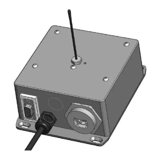
Wireless Wind Speed d. There should be a clear and unobstructed Wireless Wind Speed line of sight between the wind speed Sensor GS020 Sensor GS020 sensor antenna and the cabin mounted display unit. Mounting rod Figure: GS020 wireless wind speed sensor 1. -
Page 12: Maintenance
MAINTENANCE MAINTENANCE Replacing the Sensor 5. Install the new battery: insert the positive end and Replacing the Sensor then push in the direction of the positive pole. Battery Battery Note: A 3.6 volt lithium “D” cell battery will provide about two years of battery life, while an alkaline “D” IMPORTANT! Protect the interior of the cell battery will provide less than one year of sensor from dirt and humidity at all times. -
Page 13: Replacing The Sensor Antenna
Replacing the Sensor 7. Slide the white nylon hex bolt to the middle of Replacing the Sensor the length of the new antenna. Antenna Antenna 8. Coat the exposed metal foot of the new antenna Heavily damaged antennas (ripped out, sheared off, with an electrical insulating compound by wire exposed and fraying etc.) should be replaced to carefully inserting it in the mouth of the... -
Page 14: Certification Notes
However, Antenna List there is no guarantee that interference will not occur LSI P/N: TA011 in a particular installation. If this equipment does Description: 1/4 wave monopole... -
Page 15: Declaration Of Conformity
6.2a Declaration of conformity 6.2b CE Safety WARNING! When captors are used, the WARNING! The protection will be impared if ambiant temperature should not be higher the material and equipment are used in a than 84°C and the display should not be used manner not specified by the manufacturer. -
Page 16: Lsi Product Limited Warranty - 2009/02/16
(60) days, whichever is longer. LSI document) (the “Warranty Period”), when on a LSI reserves the right to require from you the user or installed and used in accordance with specifications owner of the Products, prior to determining if the Limited LSI Installer and User’s Manual, as... -
Page 17: Exclusion
EXPRESSLY DISCLAIMED. NO ORAL OR WRITTEN of the possibility of such damages. In any event, the LSI OR ITS LSI arising from any cause of action or INFORMATION OR ADVICE GIVEN BY total liability of EMPLOYEES... - Page 18 NOTES NOTES The GS221 System The GS221 System...
- Page 19 NOTES NOTES NOTES NOTES...
- Page 20 Technical support is available 24 hours a day, 7 days a week TLS_TechSupport@trimble.com © 2011, Load Systems International Inc. lifting.trimble.com GM221-02-05-07_ENG_rev20110612...
Need help?
Do you have a question about the GS Series and is the answer not in the manual?
Questions and answers