Table of Contents
Advertisement
Quick Links
Advertisement
Table of Contents

Related Manuals for Ice AP901S

Summary of Contents for Ice AP901S
- Page 2 Electrical equipment should be installed, operated, serviced, and maintained only by qualified personnel. Local safety regulations should be followed. No responsibility is assumed by ICE for any consequences arising out of the use of this material. We reserve right to changes without further notice.
-
Page 3: Table Of Contents
Instruction manual – AP901S Arc Protection Unit 3 (43 TABLE OF CONTENTS 1 ABBREVIATIONS ......................5 2 GENERAL ......................... 6 Arc protection unit AP901S features ................. 6 Simplified block diagram ..................8 3 OPERATION AND CONFIGURATION ................9 LED indicator functions .................... 9 LED Operation Quick Guide ................... - Page 4 Instruction manual – AP901S Arc Protection Unit 4 (43 10.4 Test plan example ....................38 11 TROUBLESHOOTING GUIDE ..................39 12 TECHNICAL DATA ......................40 12.1 Protection ....................... 40 12.2 Auxiliary voltage ..................... 40 12.3 Trip relays T1, T2, T3 ..................... 40 12.4 Binary Output BO1, BO2 and BO3 .................
-
Page 5: Abbreviations
Instruction manual – AP901S Arc Protection Unit 5 (43 BBREVIATIONS CB – Circuit breaker CBFP – Circuit breaker failure protection EMC – Electromagnetic compatibility EPROM – Erasable programmable read only memory HW – Hardware LED – Light emitting diode LV – Low voltage ms –... -
Page 6: General
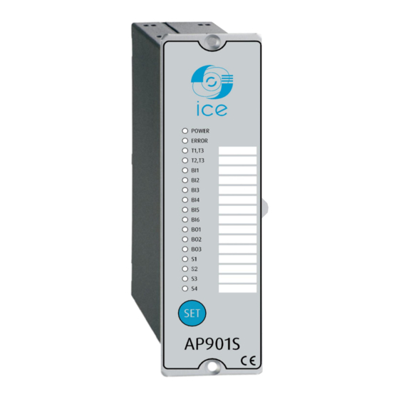
RC PROTECTION UNIT FEATURES AP901S is a multipurpose arc flash protection unit and can be applied for variety of applications that requires a large number of data communication. AP901S can be used as a stand-alone unit or as part of a more complex arc protection system through the binary bus. Main features... - Page 7 Instruction manual – AP901S Arc Protection Unit 7 (43 Figure 2-1: AP901S Arc protection IO unit A1027A...
-
Page 8: Simplified Block Diagram
Instruction manual – AP901S Arc Protection Unit 8 (43 IMPLIFIED BLOCK DIAGRAM AP901S simplified block diagram in Figure 2-2 shows the main components of the AP901S unit. Figure 2-2: AP901S simplified block diagram A1027A... -
Page 9: Operation And Configuration
PERATION AND CONFIGURATION INDICATOR FUNCTIONS AP901S contains 17 indication LEDs. A user definable text pocket can be slid in for identifying each LED function (except Power and Error LEDs). LED’s are located at the front plate of the unit for clear viewing without a need for opening doors. -
Page 10: Led Operation Quick Guide
Instruction manual – AP901S Arc Protection Unit 10 (43 LED O PERATION UICK UIDE STEADY BLINKING ACTION IF ABNORMAL POWER Auxiliary supply Auxiliary power Check the power source Blue disconnected connected Configuration Verify system condition. see chapter ERROR System healthy System failure mismatch. -
Page 11: Push-Button Description
The initialization sequence is performed by pressing the “SET”-button for 2 seconds, and the AP901S sensor LEDs and all binary LEDs start blinking. The unit scans these inputs to see if they are connected and when input is detected the corresponding LEDs are lit up to mark that a connection was found. -
Page 12: Reset
The dipswitch number 1...4 are used as scheme selection. The scheme number is according to binary arithmetic. Dipswitches are located at the back of the unit for easy access. See Figure 3-1: AP901S dipswitch and Table 3-2 AP901S dipswitch setting for details of settings. - Page 13 Instruction manual – AP901S Arc Protection Unit 13 (43 Dipswitch Function selection ON (LEFT OFF (RIGHT POSITION) POSITION) Sensor channels S2, S3, Trip on light only (L>). Trip on light and S4 trip criteria overcurrent (L> + I>). L> / L>+I>...
-
Page 14: Scheme Select Dip-Switch Settings
Logic scheme 1 The AP901S scheme 1 is utilized in selective arc protection solution. The point sensor S1 monitors the outgoing feeder cable compartment. S2 is used for monitoring the corresponding feeder breaker compartment. S3 and S4 monitor the busbar compartment. - Page 15 Logic scheme 2 The AP901S scheme 2 is utilized in selective arc protection solution. S2 is used for monitoring the incoming feeder breaker compartment. S3 monitors reserve busbar; S4 monitors the main busbar compartment. The contact T1 is responsible for tripping section circuit breaker.
- Page 16 Logic scheme 3 The AP901S scheme 3 is very similar to scheme 2. S2 is used for monitoring the incoming feeder breaker compartment. S3 monitors reserve busbar; S4 monitors the main busbar compartment. The contact T1 is responsible for tripping section circuit breaker. T2 is responsible for tripping coupler circuit breaker.
- Page 17 17 (43 Logic Scheme 4 The AP901S scheme 4 is used as intermediate unit. Sensors are monitoring section circuit breaker and the busbar between the section circuit breaker. BI3 and BI4 receive over current information from two main busbar sections reprehensively. BO1 and BO3 represent the arc fault detected at both main busbar sections.
- Page 18 18 (43 Logic Scheme 5 The AP901S scheme 5 is used in single busbar arc protection solution. Sensors are monitoring section circuit breaker and the busbar between the section circuit breaker. BI1 and BI2 receive MT signal from both incoming AP910P units. BI3 and BI4 receive overcurrent information from both incoming AP910P units.
- Page 19 19 (43 Logic Scheme 6 The AP901S scheme 6 is used in double busbar without BS & BC arc protection solution. Sensors are monitoring incomer circuit breaker, main busbar and reserve busbar. S2 monitors incomer CB. S3 monitors reserve busbar and S4 monitors main busbar. BI1 and BI2 are responsible for recognizing the incoming circuit breaker position.
- Page 20 20 (43 Logic Scheme 7 The AP901S scheme 7 is utilized in selective arc protection solution. The point sensor S1 monitors the outgoing feeder cable compartment. S2 is used for monitoring the corresponding feeder breaker compartment. S3 and S4 monitor the busbar compartment.
- Page 21 21 (43 Logic Scheme 9 The AP901S scheme 9 is utilized in selective arc protection solution. The point sensor S1 monitors the outgoing feeder cable compartment. S2 is used for monitoring the corresponding feeder breaker compartment. S3 and S4 monitor the busbar compartment.
- Page 22 22 (43 Logic Scheme 10 The AP901S scheme 10 is utilized in selective arc protection solution. S2 is used for monitoring the incoming feeder breaker compartment. S3 monitors reserve busbar; S4 monitors the main busbar compartment. The contact T1 is responsible for tripping section circuit breaker.
- Page 23 23 (43 Logic Scheme 11 The AP901S scheme 11 is very similar to scheme 10. S2 is used for monitoring the incoming feeder breaker compartment. S3 monitors reserve busbar; S4 monitors the main busbar compartment. The contact T1 is responsible for tripping section circuit breaker. T2 is responsible for tripping coupler circuit breaker.
-
Page 24: Non-Volatile Memory
Instruction manual – AP901S Arc Protection Unit 24 (43 VOLATILE MEMORY All critical system data including dipswitch settings and auto-configuration file described in chapter 3.3.1 are stored in EPROM non-volatile memory to ensure correct operation and full self-supervision even if auxiliary power is lost temporarily. -
Page 25: Arc Sensors
The detailed instructions are described in “Arc Sensors Series – Instruction booklet”. ENSOR EPENDENCIES Different sensor types can be utilized with the AP901S arc flash protection unit. The table below describes the dependencies. AS01 AS02... -
Page 26: System Self-Supervision
LED will remain as blinking status. This means that SF relay will energize and the error led will turn off. If one or more of the sensors are disconnected the healthy sensors remain in use and unit remains operational accordingly. The AP901S will remain in error mode until the disconnected sensors are repaired. -
Page 27: Application Examples
OUBLE USBAR APPLICATION WITH CURRENT AND LIGHT CONDITION AP901S may be applied requiring both overcurrent and arc light conditions for trip. In this case tripping is performed only if both conditions are fulfilled simultaneously. Typically the overcurrent condition is obtained from the AP910 unit or monitored by NP900 Series protection relays also (e.g. - Page 28 Instruction manual – AP901S Arc Protection Unit 28 (43 Figure 6-1 Double Busbar Application A1027A...
-
Page 29: Connections
Instruction manual – AP901S Arc Protection Unit 29 (43 ONNECTIONS Figure 7-1: AP901S terminals at rear plate A1027A... -
Page 30: Outputs
T1, T2 RIP RELAYS The AP901S unit has integrated trip relays T1 and T2 for tripping of the circuit-breakers. T1 and T2 relays are normally open type (NO). Trip relay T4 is a common trip relay that operates anytime T1 or T2 relay operates and can be used either for tripping one more disconnecting device or for trip alarm to local or remote monitoring and alarming system. -
Page 31: Binary Inputs Bi1, Bi2, Bi3, Bi4, Bi5 And Bi6
BI1, BI2, BI3, BI4, BI5 INARY INPUTS AP901S contains six binary inputs. Typically, BI1 and BI2 are reserved for breaker position signal information. In the most application the BI3 is responsible for receiving overcurrent from AP910P. The BI4, BI5 and BI6 can be used for receiving a trip signal or arc light signal. See chapter 3.5 Dipswitch settings. -
Page 32: Wiring Diagram
Instruction manual – AP901S Arc Protection Unit 32 (43 IRING DIAGRAM Figure 8-1: Wiring diagram of AP901S unit. A1027A... -
Page 33: Dimensions And Installation
Instruction manual – AP901S Arc Protection Unit 33 (43 IMENSIONS AND INSTALLATION AP901S is either door mounted or panel mounted in standard 19 inch rack (height of 4U and 1/8 of a unit wide). Figure 9-1: AP901S dimensions in millimetres (side view) - Page 34 Instruction manual – AP901S Arc Protection Unit 34 (43 Figure 9-2: AP901S cut out for panel mounting (millimetres) A1027A...
-
Page 35: Testing
10 T ESTING It is recommended that the AP901S unit is tested prior to substation energizing. Testing is carried out by simulating arc light to each sensor and verifying the tripping and LED indication. For arc light simulation uses a superior camera flash type: Canon Speedlite 430EX or equivalent. -
Page 36: Carrying Out Testing In Light And Current Mode
Instruction manual – AP901S Arc Protection Unit 36 (43 10.2 C ARRYING OUT TESTING IN LIGHT AND CURRENT MODE Check that the dipswitch setting positions are in accordance with your application Activate the camera flash within 20cm (12 inches) of the AS01 sensor unit and activate the binary input BI3 used for overcurrent condition simultaneously. -
Page 37: Testing Arc Flash Protection Unit Operation Time
10.3 T ESTING ARC FLASH PROTECTION UNIT OPERATION TIME The AP901S operation time test is not required at commissioning as it is performed by the manufacturer as a type test and routine production test. Refer to routine test reports sent with AP901S unit and consult your nearest ICE representative for type test reports. -
Page 38: Test Plan Example
Instruction manual – AP901S Arc Protection Unit 38 (43 10.4 T EST PLAN EXAMPLE Date: Substation Switchgear: AP901S serial number: Preconditions Light only Light + current Remark Sensor channel 1 setting Sensor channel 2,3,4 setting CBFP time setting* (Yes/No): 100ms:________ /150ms:________... -
Page 39: Troubleshooting Guide
Instruction manual – AP901S Arc Protection Unit 39 (43 11 T ROUBLESHOOTING GUIDE Problem Check Cross reference Sensor does not activate when Sensor cable wiring Chapter 4 of this manual testing Camera (or other test equipment) Chapter 10 of this manual... -
Page 40: Technical Data
Instruction manual – AP901S Arc Protection Unit 40 (43 12 T ECHNICAL DATA 12.1 P ROTECTION Trip time using mechanical trip relays 7ms* Reset time (arc light stage) Protection operational after power up 88ms *total trip time using arc light (L>) or phase/residual overcurrent (I>) from AP910 and arc light (L>) 12.2 A... -
Page 41: Binary Inputs Bi1, Bi2, Bi3, Bi4, Bi5 And Bi6
Instruction manual – AP901S Arc Protection Unit 41 (43 12.5 B BI1, BI2, BI3, BI4, BI5 INARY NPUTS Rated voltage 24 or 110 or 220Vdc Threshold Pick up ≥ 16Vdc or 88Vdc or 178 Vdc Threshold Drop off ≤ 15Vdc or 75Vdc or 155 Vdc... -
Page 42: Mechanical Tests
Instruction manual – AP901S Arc Protection Unit 42 (43 12.8 M ECHANICAL TESTS Vibration test 10…150Hz,0.07mm,0.5g (60…150Hz) 10…150Hz, 1g (10…150Hz) Shock/Bump test acc. to IEC 60255- 20g, 1000 bumps/dir. 21-2 12.9 C ASING AND PACKAGE Protection degree (front) IP 50... - Page 43 Instruction manual – AP901S Arc Protection Unit 43 (43 A1027A...
Need help?
Do you have a question about the AP901S and is the answer not in the manual?
Questions and answers