Table of Contents
Advertisement
Quick Links
Advertisement
Table of Contents

Related Manuals for Ice AP902

Summary of Contents for Ice AP902
- Page 2 Electrical equipment should be installed, operated, serviced, and maintained only by qualified personnel. Local safety regulations should be followed. No responsibility is assumed by ICE for any consequences arising out of the use of this material. We reserve right to changes without further notice.
-
Page 3: Table Of Contents
Instruction manual – AP902 Arc Protection Unit 3 (35 TABLE OF CONTENTS 1 ABBREVIATIONS ......................5 2 GENERAL ......................... 6 Arc protection unit AP902 features ................7 Simplified block diagram ..................8 3 OPERATION AND CONFIGURATION ................9 LED indicator functions .................... 9 LED Operation Quick Guide ................... - Page 4 Instruction manual – AP902 Arc Protection Unit 4 (35 10.3 Testing the CBFP function ..................29 10.4 Testing arc flash protection unit operation time ............29 10.5 Test plan example ....................30 11 TROUBLESHOOTING GUIDE ..................31 12 TECHNICAL DATA ......................32 12.1 Protection .......................
-
Page 5: Abbreviations
Instruction manual – AP902 Arc Protection Unit 5 (35 BBREVIATIONS CB – Circuit breaker CBFP – Circuit breaker failure protection EMC – Electromagnetic compatibility EPROM – Erasable programmable read only memory HW – Hardware LED – Light emitting diode LV – Low voltage ms –... -
Page 6: General
AP902 is designed according to the latest protection relay standards and is hence suitable for installations in rough environments, such as utility, traditional or renewable power plants, off shore, marine, oil and gas, mining, steel or any other heavy industry applications and as well commercial and institutional electrical systems. -
Page 7: Arc Protection Unit Ap902 Features
AP902 is a multipurpose arc flash protection unit and can be applied for variety of applications. AP902 can be used as a stand-alone unit or as part of a more complex arc protection system through the binary bus. Main features of AP902:... -
Page 8: Simplified Block Diagram
Instruction manual – AP902 Arc Protection Unit 8 (35 2.2 S IMPLIFIED BLOCK DIAGRAM AP902 simplified block diagram in Figure 2-2 shows the main components of the AP902 unit. Figure 2-2 AP902 simplified block diagram A1008B... -
Page 9: Operation And Configuration
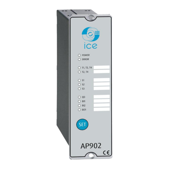
3.1 LED INDICATOR FUNCTIONS AP902 contains 11 indication LEDs. A user definable text pocket can be slid in for identifying each LED function (except Power and Error LEDs). LED’s are located at the front plate of the unit for clear viewing without a need for opening doors. -
Page 10: Led Operation Quick Guide
Instruction manual – AP902 Arc Protection Unit 10 (35 3.2 LED O PERATION UICK UIDE STEADY BLINKING ACTION IF ABNORMAL POWER Auxiliary supply Auxiliary power Check the power source Blue disconnected connected ERROR System healthy System failure Configuration Verify system condition. see chapters 11: System self- mismatch. -
Page 11: Push-Button Description
The initialization sequence is performed by pressing the “SET”-button for 2 seconds, and the AP902 sensor LEDs and BI1/BI2 LEDs start blinking. The unit scans these inputs to see if they are connected and when input is detected the corresponding LEDs are lit up to mark that a connection was found. -
Page 12: Dipswitch Settings
Also the CBFP time can be selected by dipswitch setting according to the requirement of the CBFP function. Dipswitches are located at the back of the unit for easy access. See Figure 3-1 AP902 dipswitches and Table 3-2 AP902 dipswitch setting for details of settings. - Page 13 Refer to chapter 3.5.1 and 6 Refer to chapter 3.5.1 and 6 Scheme select Table 3-2 AP902 dipswitch setting selection The chapter 3.5.1 shows AP902 internal logic and dipswitch selections. For inputs and outputs descriptions refer to chapter 7. A1008B...
-
Page 14: Scheme Select Dip-Switch Settings
Logic scheme 0 The AP902 logic scheme 0 can be not only applied as stand-alone arc protection unit, but also widely used as non-selective outgoing feeder compartment protection. Depend on this scheme, user can either select light only mode or arc light + overcurrent mode to trip all circuit breakers. -
Page 15: Non-Volatile Memory
Logic scheme 1 The AP902 logic scheme I is mainly utilized in selective arc protection solution. The fiber sensor S1 monitors the outgoing feeder cable compartment. The fiber sensor S2 monitors the corresponding feeder breaker compartment and busbar compartment. Trip contact T1 is responsible for tripping circuit breaker of the outgoing feeder. -
Page 16: Arc Sensors
The detailed instructions are described in “Arc Sensors Series - Instruction booklet”. 4.1 S ENSOR EPENDENCIES Different sensor types can be utilized with the AP902 arc flash protection unit. The table below describes the dependencies. AS01 AS02 AS06 AS07... -
Page 17: System Self-Supervision
This means that SF relay will energize and the error led will turn off. If one or more of the sensors are disconnected the healthy sensors remain in use and unit remains operational accordingly. The AP902 will remain in error mode until the disconnected sensors are repaired. -
Page 18: Application Examples
6.1 MV APPLICATION WITH CURRENT AND LIGHT CONDITION AP902 may be applied requiring both overcurrent and arc light conditions for trip. In this case tripping is performed only if both conditions are fulfilled simultaneously. Typically the overcurrent condition is obtained from the AP910 unit and the trip relay will be activated in 7ms. -
Page 19: Circuit Breaker Failure Protection (Cbfp)
Breaker failure function is activated if AP902 detects the presence of light after a set operate time. When AP902 is set to operate on light and current both parameters must persist to activate CBFP. -
Page 20: Connections
Instruction manual – AP902 Arc Protection Unit 20 (35 ONNECTIONS Figure 7-1: AP902 terminals at rear plate A1008B... -
Page 21: Outputs
7.1 O UTPUTS 7.1.1 T RIP RELAYS The AP902 unit has integrated trip relays T1 and T2 for tripping of the circuit-breakers. T1 and T2 relays are normally open type (NO). 7.1.2 T RIP RELAYS T3 relay output may act either as an electronic lock-out relay or as a trip relay. This option must be specified when ordering. -
Page 22: Inputs
S1, S2, S3 RC FIBER OPTIC LOOP SENSOR CHANNELS AP902 has 3 fiber optic loop sensor channels with transceivers and receivers (Tx, Rx). When the fiber optic loop sensor is connected to the unit one end is connected to Tx and another to Rx. -
Page 23: Auxiliary Voltage
Instruction manual – AP902 Arc Protection Unit 23 (35 7.3 A UXILIARY VOLTAGE The auxiliary power supply voltage is 80….265Vac/dc. Optionally an 18…72Vdc version is available. After powering up the unit protection is active and operational within 50ms. A1008B... -
Page 24: Wiring Diagram
Instruction manual – AP902 Arc Protection Unit 24 (35 IRING DIAGRAM Figure 8-1: Wiring diagram of AP902 unit. A1008B... -
Page 25: Dimensions And Installation
Instruction manual – AP902 Arc Protection Unit 25 (35 IMENSIONS AND INSTALLATION AP902 is either door mounted or panel mounted in standard 19 inch rack (height of 4U and 1/8 of a unit wide). Figure 9-1: AP902 dimensions in millimetres (side view) - Page 26 Instruction manual – AP902 Arc Protection Unit 26 (35 Figure 9-2: AP902 cut out for panel mounting (millimeters) A1008B...
-
Page 27: Testing
10 T ESTING It is recommended that the AP902 unit is tested prior to substation energizing. Testing is carried out by simulating arc light to each sensor and verifying the tripping and LED indication. For arc light simulation a superior camera flash type is used: Canon Speedlite 430EX or equivalent. -
Page 28: Carrying Out Testing In Light And Current Mode
Instruction manual – AP902 Arc Protection Unit 28 (35 10.2 C ARRYING OUT TESTING IN LIGHT AND CURRENT MODE Check that the dipswitch setting positions are in accordance with your application. Activate the camera flash within 20cm (12 inches) of the arc light fiber optic loop sensor units and activate the binary input BI1 used for overcurrent condition simultaneously. -
Page 29: Testing The Cbfp Function
10.4 T ESTING ARC FLASH PROTECTION UNIT OPERATION TIME The AP902 operation time test is not required at commissioning as it is performed by the manufacturer as a type test and routine production test. Refer to routine test reports sent with AP902 unit and consult your nearest ICE representative for type test reports. -
Page 30: Test Plan Example
Instruction manual – AP902 Arc Protection Unit 30 (35 10.5 T EST PLAN EXAMPLE Date: Substation Switchgear: AP902 serial number: Preconditions Light only Light + Remark current Sensor channel 1 setting Sensor channel 2 setting Sensor channel 3 setting Master trip... -
Page 31: Troubleshooting Guide
Instruction manual – AP902 Arc Protection Unit 31 (35 11 T ROUBLESHOOTING GUIDE Problem Check Cross reference Refer to « Arc Sensors Series - Fiber sensor connection Instruction booklet » Sensor does not activate when testing Camera (or other test equipment) -
Page 32: Technical Data
Instruction manual – AP902 Arc Protection Unit 32 (35 12 T ECHNICAL DATA 12.1 P ROTECTION Trip time using mechanical trip relays 7ms* Reset time (arc light stage) Protection operational after power up 88ms *total trip time using arc light (L>) or phase/residual overcurrent (I>) from AP910 and arc light (L>) 12.2 A... -
Page 33: Disturbance Tests
Instruction manual – AP902 Arc Protection Unit 33 (35 12.6 D ISTURBANCE TESTS EMC test CE approved and tested according to EN 50081-2, EN 50082-2 Emission - Conducted (EN 55011 class A) 0.15 – 30MHz - Emitted (EN 55011 class A) -
Page 34: Environmental Conditions
Instruction manual – AP902 Arc Protection Unit 34 (35 12.10 E NVIRONMENTAL CONDITIONS Specified ambient service temp. range -35…+70°C Transport and storage temp. range -35…+70°C Relative humidity Up to 97% A1008B... - Page 35 Instruction manual – AP902 Arc Protection Unit 35 (35 A1008B...
Need help?
Do you have a question about the AP902 and is the answer not in the manual?
Questions and answers