
Related Manuals for Misterstep EXTERIOR ZINK

Summary of Contents for Misterstep EXTERIOR ZINK
- Page 1 EXTERIOR ZINK ISTRUZIONI DI POSA ASSEMBLY INSTRUCTIONS INSTRUCTIONS DE MONTAGE INSTRUCCIONES PARA LA COLOCACION MONTAGEANLEITUNG INSTRUÇÕES DE INSTALAÇÃO ...
- Page 2 ...
- Page 3 Exterior Zink Descrizione Scala a chiocciola modulare per esterni a pianta circolare con gradino in lamiera bugnata. La struttura portante è composta da un palo centrale in acciaio rivestito con distanziatori interposti fra i gradini. L’alzata è regolabile attraverso distanziali in plastica filettati. La ringhiera è a colonnine con corrimano plastica. La resistenza agli agenti atmosferici è realizzata tramite: • il trattamento di zincatura a caldo di tutti gli elementi metallici a vista (gradino, fusto e colonnine ringhiera) cataforesi per i componenti interni (Palo centrale, vitone, boccola filettata) ...
- Page 4 Colori Grigio zincato naturale NOTA BENE E’ anche possibile verniciare la scala autonomamente subito dopo l’assemblaggio, utilizzando un primer adatto, oppure dopo un’esposizione agli agenti atmosferici non inferiore a 12 mesi. Packing Confezione scala completa 12 gradini + 1 sbarco Kit Palo Aggiuntivo Kit Fermo Block Kit Gancio Kit Colonna Stop Kit Balaustra 1 mt Kit Gradino Supplementare Ø1200 Kit Gradino Supplementare Ø1400 Kit Gradino Supplementare Ø1600 Note E’ caratteristica dei prodotti zincati a caldo presentare piccole zone in cui l’adesione di zinco non è perfetta. E’ possibile, inoltre, che si danneggi la superficie zincata durante il montaggio. A garanzia di una lunga durata del prodotto è compresa nella fornitura una confezione di zinco spray, applicabile a pennello, per eventuali ritocchi dopo l’assemblaggio. Consigliamo di verificare periodicamente l’integrità della scala ritoccando eventuali punti danneggiati con prodotti analoghi, reperibili in commercio. E’ caratteristica dei ...
- Page 5 NOTE PER LA POSA Prima di iniziare il montaggio della scala verificare sempre la capacità di carico del pavimento. Tutte le parti metalliche zincate sono a misura. Nessuna parte metallica deve essere assolutamente, forata, tagliata, ecc., per evitare l’insorgere della ruggine, ad eccezione di Gancio e Fermo Block. Struttura e gradini 1) Preparare i gradini intermedi e quello di sbarco, assemblando nei fori appositi le boccole in plastica per l’inserimento delle colonne passanti. Il foro presente nella boccola sotto al gradino, deve essere orientato verso il centro gradino al fine di permettere un semplice e corretto serraggio della rondella quadrata sulla colonna. Nota: l'inserimento della rondella quadrata e del grano avviene subito e si deve fare attenzione a non avvitare troppo il dado, in modo da mantenerlo comunque in sede, ma tale da evitare graffi sulla colonna passante al momento del suo inserimento ...
- Page 6 12) Le colonne della ringhiera hanno diverse altezze in funzione del diametro scala. Verificarne l’esatto posizionamento, come da schema. Alzata 210: fare scorrere le colonne centrali attraverso l’asola, portandole alla massima distanza fra loro. Alzata 220: tenere le colonne centrali nella mezzeria dell’asola, formando tre interassi uguali. Alzata 230: scorrere le colonne centrali attraverso l’asola, portandole alla minima distanza fra loro. Regolare di conseguenza le colonne passanti facendole scorrere in altezza. 13) Disporre le colonne sul gradino di sbarco e inserirvi le cime: in corrispondenza del foro con la boccola utilizzare la colonna da 964 mm fornita nel kit. Assemblare i corrimani alle colonne, fissando le cime con le apposite viti. (Il tratto di corrimano fornito nell’imballo della scala è sufficiente per 2 gradini supplementari). ...
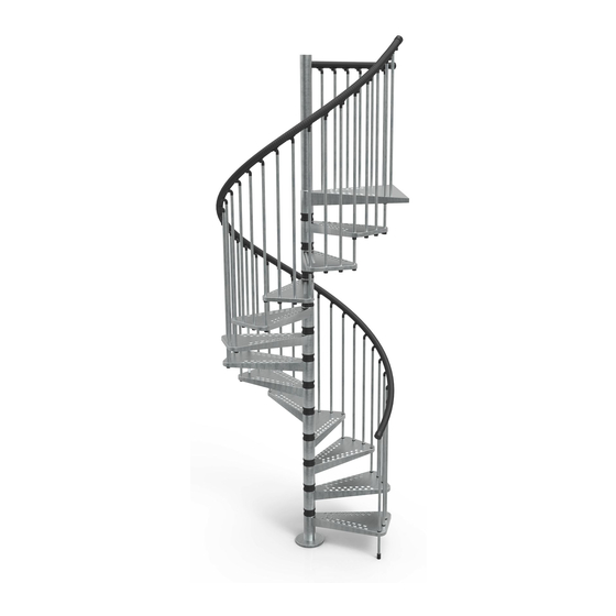
- Page 7 Exterior Zink Description Modular spiral staircase for outdoors with a circular plan and embossed metal plate step. The support structure is composed of a central steel pole covered with spacers interposed between the steps. The riser is adjustable using threaded plastic spacers. The railing is made up of columns with a plastic handrail. Weather resistance is achieved through: ‐ hot dip galvanising of all exposed metal parts (step, shaft and railing columns) ‐ internal components treated with cataphoresis (central pole, auger, threaded bushing) system ‐ the use of stainless steel bolts and hardware. ‐ the use of plastic parts. The embossing on the walkways gives greater stiffness, non‐slip properties and greater resistance to footfall. Riser Adjustable from a minimum of 21 cm to a maximum of 23 cm using the plastic threaded spacers. Tread Step angle: 30° Landing angle: 60° Landing Type of landing: only flush to floor, straight head. Staircase diameter 120, 140, 160 cm. Steps and structure No. of steps 12 + 1 in printed sheet metal welded to the spacer tube. Overall height (HT): from 273 to 299 cm Step material: Fe P13 (UNI 5867 EN111) Spacer tube material: S235‐JR (EN 10027) Surface treatment: Nylon 6.6 ‐ Black ...
- Page 8 Colours Natural galvanised grey N.B. It is also possible to paint the staircase autonomously immediately after assembly, using a suitable primer, or after exposure to weather for at least 12 months. Packing Complete staircase kit with 12 steps + 1 landing Additional Pole Kit Fermo Block (column to wall connection) Kit Gancio (stair column to balustrade column connection) Kit Stop Column Kit Balustrade Kit 1 m Extra Step Kit Ø1200 Extra Step Kit Ø1400 Extra Step Kit Ø1600 Remarks A feature of hot dip galvanised products is small areas where the adhesion of zinc is not perfect. It is also possible that the galvanised surface is damaged during assembly. To guarantee a long product life, a bottle of spray zinc is included, and can be applied by brush to make small touch‐ups after assembly. We recommend that you periodically check the integrity of the staircase, touching up any damaged spots with similar products available on the market. A feature of hot dip galvanised products is that they become dull over time, due to a normal process of oxidation of the zinc exposed to the weather. It is possible to paint the staircase immediately after assembly, using a suitable primer or, without special precautions, after exposure to the weather of at least 12 to 18 months. HT – Total height from floor to floor HPS – Height from lower floor to ceiling S – Floor thickness (HT‐HPS) A – Riser QG – Height of the first step inside the hole HP – Passage height in the hole (HPS‐QG) 2012©Rintal S.p.a–Tutti i diritti riservati–All rights riserved FM_Exterior-Zink_R2_12/12...
-
Page 9: Notes For Installation
NOTES FOR INSTALLATION Before positioning the stair, always check the bearing capacity of the pavement. All galvanised metal parts are made to size. Under no circumstance must any metal part be pierced, cut etc. to prevent the onset of rust, with the exception of the Gancio and the Fermo Block. Structure and steps 1) Prepare the intermediate steps and the landing, assembling the plastic bushing in the special holes for insertion of the through‐columns. Direct the hole on the bush for the insertion of the locking dowel toward the center of the step. 2) Assemble the pole in the sequence indicated, locking the elements firmly together, levering using a pin in the holes in the tubes. 3) Position the pole in relation to the hole, placing the landing step on the exit side of the staircase. Check for exact perpendicularity to the floor. Before securing the platform, make sure of its perfect horizontality by the use of the level tube. Before taking the measure of the holes in the floor for the center pole, block temporarily the platform on the pole to avoid traveling and measurement errors. 4) Secure the plate using screws and dowels. In the case of wooden floor/slab use only screws for wood, of the hanger bolt/leg bolt type, to replace those provided exclusively suited to reinforced concrete. 5) Adjust the plastic spacers by tightening the threaded ring nut, leaving a distance of A‐170 between the two beats. (Remember that A = HT/n° steps). Attention. In the first rise, from the average height of the plastic spacer must be deducted the thickness of the central pole plate. ... - Page 10 between them. Riser 220: keep the central columns in the middle of the slot, forming three equal distances between centres. Riser 230: slide the central columns through the slot, bringing them to the minimum distance between them. Adjust the through‐columns accordingly, sliding them upwards. 13) Arrange the columns on the landing step and insert the tops. Secure the handrails to the columns, fixing the tops with the relative screws. (The section of handrail supplied in the staircase package is enough for 2 additional steps). For the platform railing, in correspondence of the plastic bush us the baluster 964 mm long that is specially provided in the kit. Fix the provided baluster‐floor fixing element to block the last passing baluster on the landing platform (on the opposite side of the platform railing). The handrail must be fixed first to the passing balusters and secondly to the central balusters of the step. 2012©Rintal S.p.a–Tutti i diritti riservati–All rights riserved FM_Exterior-Zink_R2_12/12...
- Page 11 Exterior Zink Fiche technique Description Escalier hélicoïdal modulaire pour extérieur à base circulaire avec marche en tôle larmée. La structure portante est constituée par un poteau central en acier revêtu avec des entretoises interposées entre les marches. La hauteur de la marche est réglable au moyen d’entretoises en plastique filetées. La rampe est à balustres avec main courante en plastique. La résistance aux agents atmosphériques est réalisée au moyen de: ...
-
Page 12: Dimensions D'encombrement
Dimensions d’encombrement Diamètre nominal Avec garde‐corps marche (cm) Diamètre trou Dépass. (mm) minimum (mm) 120 1250 25 140 1450 25 160 1650 25 Couleurs Gris zingué naturel NOTA BENE Il est aussi possible de vernir l’escalier de façon autonome après l’assemblage, en utilisant un primaire approprié, ou bien après une exposition aux agents atmosphériques non inférieure à 12 mois. Emballage Emballage de l’échelle complète 12 marches + 1 palier d’arrivée Kit Poteau supplémentaire Kit Fermo Block (arrêtoir de blocage) Kit Crochet Kit Colonne Stop Kit Balustrade 1 m. Kit Marche Supplémentaire Ø1200 Kit Marche Supplémentaire Ø1400 Kit Marche Supplémentaire Ø1600 Notes C’est une caractéristique des produits zingués à chaud de présenter de petites zones où l’adhésion de zinc n’est pas parfaite. Il est possible, en outre, que la surface zinguée puisse s’endommager pendant le montage. Comme garantie ... - Page 13 HT – Hauteur totale de plancher à plancher HPS – Hauteur du plancher inférieur au plafond S – Épaisseur du plancher (HT‐HPS) A – Entremarche QG – Hauteur de la première marche à l’intérieur du trou HP – Dimension de passage du trou (HPS‐QG) NOTES POUR LA POSE Toutes les parties métalliques zinguées sont usinées à longueur précise. Aucune partie métallique ne doit être pour aucune raison, percée, coupée, etc.…, pour éviter la formation de rouille, à l’exception du Crochet et de l’Arrêtoir de Blocage. Structure et marches 1) Préparer les marches intermédiaires et le palier d’arrivée, en assemblant dans les trous relatifs les douilles en plastique pour l’introduction des balustres passants. ...
- Page 14 Ne pas bloquer “définitivement” les balustres à la marche, vu qu’ils devront subir des réglages successifs pendant la pose, pour leur positionnement correct. 9) Introduire les balustres sur toutes les marches, bloquer les balustres passants avec les goujons filetés, et ceux sur la marche avec les dispositifs de fixation en matière plastique. 10) Composer le sommet de la colonne et bloquer définitivement à la main courante, en inclinant selon l’inclinaison de l’escalier. 11) Le premier balustre de l’escalier doit être fixé au sol. 12) Les balustres de la rampe ont des hauteurs différentes en fonction du diamètre de l’escalier. Vérifier le positionnement exact, en se référant au schéma. Hauteur de marche 210: faire coulisser les balustres centraux à travers la fente, en les portant au maximum de la distance entre eux. Hauteur de marche 220: maintenir les balustres centraux dans la ligne médiane de la fente, en formant ainsi trois entraxes égaux. V230: faire coulisser les balustres centraux à travers la fente, en les portant à la distance minimum entre eux. Régler par conséquent les balustres passants en les faisant coulisser en hauteur. 13) Disposer les balustres sur la marche d’arrivée et introduire les extrémités supérieures. Assembler les mains courantes aux balustres, en fixant les parties supérieures avec les vis relatives. (le bout de main courante fourni dans l’emballage de l’échelle est suffisant pour 2 marches supplémentaires). 2012©Rintal S.p.a–Tutti i diritti riservati–All rights riserved FM_Exterior-Zink_R2_12/12...
- Page 15 Exterior Zink Technische Daten Beschreibung Modulare Wendeltreppe für den Außenbereich mit runder Basis aus Noppenstahlblech. Die Trägerstruktur besteht aus einer zentralen Stahlstange, die mit Abstandshaltern zwischen den Stufen versehen ist. Der Abstand zwischen zwei Stufen kann mithilfe einer Distanzmutter aus Plastik eingestellt werden. Das Geländer besteht aus Stäben mit einem Plastikhandlauf. Folgende Verarbeitung bzw. folgender Materialeinsatz tragen zur Widerstandsfähigkeit gegenüber Witterungseinflüssen bei: ...
- Page 16 Ausmaße Nominaler Durchmesser Mit Geländer Stufe (cm) Minimaler Durchmesser Öffnung Abweichung (mm) (mm) 120 1250 25 140 1450 25 160 1650 25 Farben Verzinktes natürliches Grau HINWEIS Nach dem Zusammenbau kann die Treppe auch selbst angestrichen werden. Dafür einen geeigneten Primer verwenden bzw. nachdem die Treppe den Witterungsverhältnissen mindestens 12 Monate ausgesetzt wurde, kann sie auch ohne Primer angestrichen werden. ...
- Page 17 HT – Gesamthöhe von Stockwerk zu Stockwerk HPS – Höhe vom unteren Stockwerk bis unter das Dach S – Stärke des Dachbodens (HT‐HPS) A – Stufenabstand QG – Wert der ersten Stufe in der Öffnung HP – Quota di passaggio nel foro (HPS‐QG) HINWEISE FÜR DIE MONTAGE Sämtliche verzinkte Metallteile sind auf Maß zugeschnitten. Kein Metallteil darf gelocht, geschnitten, usw. sein, um Rostbildung zu vermeiden, mit Ausnahme der Aufhängung und dem Fermo Block. Struktur und Stufen 1) Die Zwischenstufen und die Austrittstufe vorbereiten. Dafür in den Öffnung die entsprechenden Plastikhülsen für die Durchlaufstäbe zusammenbauen. ...
- Page 18 Geländer Die Stäbe des Geländers entsprechend platzieren. Dabei darauf achten, dass die Stäbe mit 116,5 cm die Durchlaufstäbe der Stufen sind. Diese Stäbe bestimmen die genaue Position der Tritte. Die Stäbe an den Stufen nicht ganz anziehen, denn während der Montage werden diese noch in ihre korrekte Position verschoben. 9) Die Stäbe in alle Stufen einfügen und die Durchlaufstäbe mit Gewindestiften festmachen. Die Stäbe an den Stufen mit der entsprechenden Plastikbefestigung anbringen. ...
- Page 19 Exterior Zink Ficha técnica Descripción Escalera de caracol modular para exteriores de planta circular con peldaño de chapa lagrimada. La estructura portante está compuesta por un poste central de acero recubierto con distanciadores interpuestos entre los peldaños. La contrahuella es regulable a través de distanciadores plásticos roscados. La baranda tiene barrotes y el pasamanos es de plástico. La resistencia a los agentes atmosféricos se realiza a través: de un tratamiento de galvanizado en caliente de todos los elementos metálicos a vista (peldaño, fuste y barrotes de la baranda). ...
- Page 20 Dimensiones generales Diámetro nominal Con baranda peldaño (en cm) Diámetro orificio Aliviadero (mm) mínimo (mm) 120 1250 25 140 1450 25 160 1650 25 Colores Gris galvanizado natural NÓTESE BIEN: también se puede pintar la escalera autónomamente inmediatamente después del ensamblaje, utilizando una pintura de fondo apropiada, o después de una exposición a los agentes atmosféricos no inferior a 12 meses. ...
- Page 21 HT – Altura total del suelo a suelo HPS – Altura del suelo inferior al techo S – Espesor del entramado (HT‐HPS) A – Contrahuella QG – Cota del primer peldaño interior del orificio HP – Cota de pasaje en el orificio (HPS‐QG) NOTAS PARA LA COLOCACIÓN Todas las partes metálicas galvanizadas se fabrican a medida. Ninguna parte metálica debe perforarse, cortarse, etc para evitar la aparición de óxido, con excepción del gancho y del retén Block. Estructura y peldaños 1) Preparar los peldaños intermedios y aquel de egreso, ensamblando en los respectivos orificios las bocas plásticas para la introducción de los barrotes pasantes. 2) Ensamblar el poste en la secuencia indicada bloqueando firmemente los elementos entre sí, haciendo palanca con un perno en los respectivos orificios de los tubos. ...
- Page 22 Baranda Predisponer los barrotes en el posicionamiento, recordando que los barrotes de 116.5 cm son aquellos pasantes entre los peldaños. Estos barrotes definen la posición exacta de las huellas. No bloquear “definitivamente” los barrotes al peldaño porque deberán someterse a otros ajustes durante la colocación para su posicionamiento correcto. 9) Colocar los barrotes en todos los peldaños, bloqueando aquellos pasantes con los tornillos prisioneros y aquellos en el peldaño con las relativas fijaciones en material plástico. 10) Colocar la cima del barrote y bloquearla definitivamente al pasamano, inclinándola según la pendiente de la escalera. 11) El primer barrote de la escalera debe fijarse en el suelo. 12) Los barrotes de la baranda tienen diferentes alturas según el diámetro de la escalera. Comprobar su posicionamiento exacto como se ilustra en el esquema. ...
- Page 23 Exterior Zinc Descrição Escadaria em espiral modular externa de planta circular com degraus em chapa estampada em relevo. A estrutura de suporte é constituída por um poste central em aço revestido com espaçadores interpostos entre os degraus. A altura do degrau é regulável através de espaçadores de plástico roscados. O parapeito é de colunas com corrimão de plástico. A resistência aos agentes atmosféricos é realizada através de: Tratamento de galvanização a quente de todos os elementos metálicos a vista (degrau, tubo e colunas do parapeito) Galvanização a frio de componentes internos (Poste central, parafuso, casquilho roscado) ...
- Page 24 Dimensões totais Diâmetro nominal com parapeito degrau (cm) Diâmetro orifício Saliência (mm) mínimo (mm) 120 1250 25 140 1450 25 160 1650 25 Cores Cinzento zincado natural NOTA BENE Também é possível pintar a escada autonomamente imediatamente após a montagem, utilizando uma primeira demão de primer adequado, ou após uma exposição aos agentes atmosféricos, não inferior a 12 meses. Embalagem Embalagem escada completa 12 degarus + 1 patamar Kit Poste Adicional Kit Bloqueador Block Kit Gancho ...
- Page 25 HT – Altura total do pavimento a pavimento HPS – Altura do pavimento inferior ao teto S – Espessura do soalho (HT‐HPS) A – Altura do degrau QG – Dimensão do primeiro degrau interno ao orifícios HP – Dimensão de passagem no orifício (HPS‐QG) NOTA PARA A INSTALAÇÃO Todas as peças metálicas galvanizadas são feitas à medida. Nenhuma parte metálica deve ser absolutamente, perfurada, cortada, etc ..., para evitar o aparecimento de ferrugem, com a exceção do Gancho e do Bloqueador Block. ...
- Page 26 Parapeito Predispor as colunas para a posição, observando que as colunas de 116.5 cm são as passantes entre os degraus. Estas colunas definem a posição exata do piso dos degraus. Não bloqueie "definitivamente" as colunas ao degrau, porque terão de sofrer regulações posteriores durante a instalação, para o correto posicionamento. 9) Insira as colunas em todos os degraus, bloqueando os passantes com as cavilhas, e aquelas dos degraus com as suas fixações em material plástico. ...
- Page 27 2012©Rintal S.p.a–Tutti i diritti riservati–All rights riserved FM_Exterior-Zink_R2_12/12...
- Page 28 2012©Rintal S.p.a–Tutti i diritti riservati–All rights riserved FM_Exterior-Zink_R2_12/12...
- Page 29 2012©Rintal S.p.a–Tutti i diritti riservati–All rights riserved FM_Exterior-Zink_R2_12/12...
- Page 30 2012©Rintal S.p.a–Tutti i diritti riservati–All rights riserved FM_Exterior-Zink_R2_12/12...
- Page 31 2012©Rintal S.p.a–Tutti i diritti riservati–All rights riserved FM_Exterior-Zink_R2_12/12...
- Page 32 2012©Rintal S.p.a–Tutti i diritti riservati–All rights riserved FM_Exterior-Zink_R2_12/12...
- Page 33 Ø 1200 Q. COD. IMAGE EXTERIOR ZINK 602042010 602121010 600230510 600231510 600231710 600232510 600233010 600340010 600343010 600356010 600490010 600496017 600497017 600498017 630103542 630132042 M8 X 40 2012©Rintal S.p.a–Tutti i diritti riservati–All rights riserved FM_Exterior-Zink_R2_12/12...
- Page 34 Ø 1200 Q. COD. IMAGE EXTERIOR ZINK 630152000 8 X 100 630133542 M10 X 80 630142042 5 X 20 630192010 M22 X 1050 630331442 8 X 24 630333042 M10 630330242 10 X 30 640052014 640067114 640067214 640067414 640067514 640071014 640076014 640079014 650800000 2012©Rintal S.p.a–Tutti i diritti riservati–All rights riserved FM_Exterior-Zink_R2_12/12...
- Page 35 Ø 1200 Q. COD. IMAGE EXTERIOR ZINK 640043014 640045014 640067814 640067914 640081514 640065214 630109242 M6 X 6 630109142 640400114 640400214 2012©Rintal S.p.a–Tutti i diritti riservati–All rights riserved FM_Exterior-Zink_R2_12/12...
- Page 36 Ø 1400 Q. COD. IMAGE EXTERIOR ZINK 602043010 602122010 600230510 600231510 600231710 600232510 600233010 600340010 600343010 600356010 600490010 600496017 600497017 600498017 630103542 630132042 M8 X 40 2012©Rintal S.p.a–Tutti i diritti riservati–All rights riserved FM_Exterior-Zink_R2_12/12...
- Page 37 Ø 1400 Q. COD. IMAGE EXTERIOR ZINK 630152000 8 X 100 630133542 M10 X 80 630142042 5 X 20 630192010 M22 X 1050 630331442 8 X 24 630333042 630330242 10 X 30 640079014 640052014 640067114 640067214 640067414 640067514 640071014 640076014 650800000 2012©Rintal S.p.a–Tutti i diritti riservati–All rights riserved FM_Exterior-Zink_R2_12/12...
- Page 38 Ø 1400 Q. COD. IMAGE EXTERIOR ZINK 640043014 640045014 640067814 640067914 640081514 640065214 630109242 M6 X 6 630109142 640400114 640400214 2012©Rintal S.p.a–Tutti i diritti riservati–All rights riserved FM_Exterior-Zink_R2_12/12...
- Page 39 Ø 1600 COD. IMAGE EXTERIOR ZINK 602044010 602123010 600230510 600231510 600232110 600232710 600233010 600340010 600343010 600356010 600490010 600496017 600497017 600498017 630103542 M8 X40 630132042 2012©Rintal S.p.a–Tutti i diritti riservati–All rights riserved FM_Exterior-Zink_R2_12/12...
- Page 40 Ø 1600 COD. IMAGE EXTERIOR ZINK M8 X 40 630133542 5 X 20 630142042 630192010 M22 X 1050 8 X 24 630331442 630333042 10 X 30 630330242 8 X 100 630152000 640052014 640067114 640067214 640067414 640067514 640071014 640076014 640079014 650800000 2012©Rintal S.p.a–Tutti i diritti riservati–All rights riserved FM_Exterior-Zink_R2_12/12...
- Page 41 Ø 1600 COD. IMAGE EXTERIOR ZINK 640043014 640045014 640067814 640067914 640081514 640065214 M6 X 6 630109242 630109142 640400114 640400214 2012©Rintal S.p.a–Tutti i diritti riservati–All rights riserved FM_Exterior-Zink_R2_12/12...
- Page 42 ...
- Page 43 ...
- Page 44 RINTAL S.P.A. VIA TRAIANO IMPERATORE, 6 47122 FORLI’ (FC) ITALY TEL. + 39.0543.791111 FAX + 39.0543.722544 www.rintal.com info@rintal.it ...
Need help?
Do you have a question about the EXTERIOR ZINK and is the answer not in the manual?
Questions and answers