Table of Contents
Advertisement
Quick Links
1.
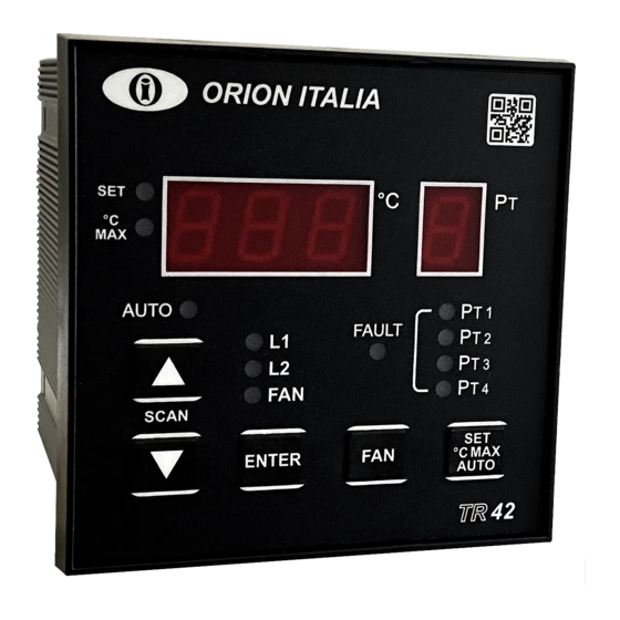
DESCRIPTION
The digital temperature relay TR-42 has been created as an accessory of main importance for resin or air insulated three-phase MT transformers, as
protection against dangerous over temperatures on the insulating coil, on the winding and to manage the intervention of cooling fans. The temperature is
detected by 3 or 4 thermal detectors PT 100, three of them located in the transformer coils, the fourth on the core.
Features
Display of the actual temperature of the 4 PT sensors.
-
Display & storage of the highest temperature of each PT sensor.
-
3 programmable output contacts from 0° to 220°C level 1, level 2 and FAN
-
control.
Automatic and "Always ON" fan mode.
-
2.
INSTALLATION
Install the equipment according to the characteristics of humidity and temperature that has been designed to work in. To avoid noise pickup and interference
the relay should be placed away from high current conductors or sources of strong magnetic fields. The device has been designed for the installation on a
panel board with a cutout of 92x92mm using the fixing accessories that come with the relay. Before proceeding with the installation that must be carried
out by a qualified technician, it is recommended to disconnect the power supply on the working area. Orion Italia urges that security procedures be followed
during this installation.
3.
WIRING CONNECTION
For the connection, follow the diagram on page 4. Herein after the description of the different electric connections:
3.1
POWER SUPPLY
The power supply range is: 24-240 Vcc/Vca (50 – 60Hz), -15%, +10% and power must be connected between the terminals 40 and 42. Note: The device does
not have internal fuses. This is to allow the selection of the desired external protection.
IMPORTANT: before doing the dielectric strength test of panel board, where the device is installed, it is necessary to disconnect it from the power line
voltage.
3.2
SENSORS CONNECTION
Each PT sensor has one white wire and two red ones according to the UNI 7937 regulation.
- Sensor cables should be made with shielded twisted pairs and the
shield should be connected to the system's ground.
- To compensate the resistance of the wire, it is necessary to connect
each sensor with three (3) wires of the same section (at least 1 mm²).
3.3
OUTPUT CONTACTS CONNECTION
In the back side of the device, it is possible to see the output contacts (in absence of power supply). The ALARM relay (L1), TRIP relay (L2) and fan control
(FAN) activate when temperature reaches the setpoint. The FAULT relay (FAULT) opens when power supply is connected and it will be closed when internal
failure occurs, failure of the PT sensors or failure of the power supply. The FAN contact can be used as a control of the cooling system. Note: When using
the contacts for control of inductive loads in Vac (coils of relays, contactors, solenoids), it is essential to limit the overcurrent, or place a R/C group in parallel
to the inductor. If it works in DC, a diode in anti-parallel should be connected.
3.4
SERIAL COMMUNICATION CONNECTION
Communication capabilities are available in the device connecting the RS-485 port in a network (up to 32 devices) controlled by a supervisor device (PC).
The protocol used is Modbus RTU. The connections must be made with shielded twisted wires.
4.
FUNCTIONS AND SIGNALS
Display: on the display °C (3 digits) you can observe the value of the temperature and program the settings; through the display PT (1 digit) you can see the
corresponding Pt Channel.
SET LED: if on, it indicates that the user is in the SET mode.
°C MAX LED: if on, it indicates that the user is in the °C MAX mode.
L1, L2 LED: if on, the temperature of one PT sensor reached the corresponding L1 or L2 programmed threshold and the corresponding relay is active.
FAN LED: if on, the "always ON" mode is active and the FAN relay will always be active. If flashing, the temperature of one PT sensor reached the
corresponding FAN programmed threshold or the weekly fan activation function is active and the FAN relay is active.
PT1, PT2, PT3, PT4 LEDs: if on, the temperature of one of the corresponding PT sensors reached the L1 or L2 programmed threshold and the corresponding
relay is active. If flashing, the respective PT sensor is in fault.
FAULT LED: if flashing, it indicates that the flashing PT1, PT2, PT3, PT4, is in fault. The fault cause will be showed through the °C display when positioned
with the arrow buttons on the faulty sensor: Fcc in case of short circuit and Fco for open circuit. Dropout condition for Fcc: T ≥ -7 °C. Dropout condition for
Fco: T ≤ 239 °C.
AUTO LED: if on, it means the user is in the AUTO SCAN mode.
HMI Test: depending on which menu the user is in, by pressing the SET, °C MAX, AUTO button and then keeping the DOWN button pressed, all LEDs and
seven segment LEDs will turn on.
SCAN, AUTO SCAN: in AUTO SCAN mode, the device will automatically scan between each PT sensor temperature showing it on the display every 5sec
allowing the user to see all the temperatures. To exit from the AUTO SCAN function, press any arrow button. The user will still be able to manually scan by
using the UP/DOWN buttons. By pressing the SET, °C MAX, AUTO button until the AUTO LED turns on, the AUTO SCAN function will reactivate. To activate
the AUTO SCAN function in °C MAX, select the °C MAX mode with the same button and keep the UP button pressed for more than 2sec.
FAN: the FAN button allows to switch between "always ON" or Automatic Fan Operation. In "always ON" mode, the fan will always be ON and the FAN LED
will be ON. In automatic mode, the fan will be ON and the FAN LED will blink when one PT sensor reaches the corresponding FAN programmed threshold.
If the setpoint FAN ACTIVATION = OFF, the manual fan will still allow the user to close/open the fan output contact.
TR-42 Temperature Protection Relay
Alarm of device failure or PT 100 disconnection or short circuit.
-
Automatic fan start every week (bearing protections).
-
Insulated RS-485 communication port.
-
Insulated 4-20mA output (Optional: see ORDER CODE).
-
- The probes wiring should be placed away from high current conductors,
high tension and from inductive elements such as remote-control switch,
etc. If the wires travel on the same route as the power lines, separate the
wires with suitable elements.
1
Instruction Manual: TR42 GBM 25/02/2021
Advertisement
Table of Contents

Subscribe to Our Youtube Channel
Related Manuals for ORION ITALIA TR42


Summary of Contents for ORION ITALIA TR42
- Page 1 92x92mm using the fixing accessories that come with the relay. Before proceeding with the installation that must be carried out by a qualified technician, it is recommended to disconnect the power supply on the working area. Orion Italia urges that security procedures be followed during this installation.
- Page 2 Set the value at which the L2 contact will close. FAN will be turned ON at this temperature. The dropout (reset) value is 2°C less than the setpoint. Note: L2 must be > L1. TR-42 Temperature Protection Relay Instruction Manual: TR42 GBM 25/02/2021...
- Page 3 : this option will scan each PT sensor every 5sec. 4mA will be applied to the output and it will be possible to correct the calibration value. : hottest PT sensor among the ones connected. TR-42 Temperature Protection Relay Instruction Manual: TR42 GBM 25/02/2021...
- Page 4 Orion Italia, S.r.l. warrants this product to be free from defects in material and workmanship. To exercise this warranty, write or call your local Orion Italia representative, or contact Orion Italia in Piacenza, Italy. You will be given prompt assistance.
Need help?
Do you have a question about the TR42 and is the answer not in the manual?
Questions and answers