Advertisement
Quick Links
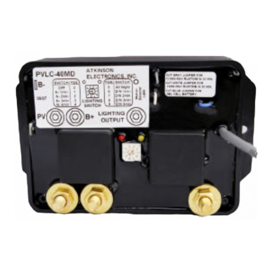
PV CHARGE & LIGHTING CONTROLLER W/ Motion Sensor 40 Amp
FEATURES
v
PV charge & lighting controller - waterproof
v
Micro-controller for digital accuracy and reliability
v
Fully automatic operation on 12/24V DC systems
v
Automatic dusk and dawn lighting control
v
Motion Sensor activated lighting control.
v
Will handle up to 40 Amps @ 28VDC from PV panels
and lighting loads up to 40 Amps
v
Built-in temperature compensation for PV charging
v
LED indication of solar charge & lighting control
v
Pulse action reduces battery sulfation
APPLICATIONS
v
Photo Voltaic charge and lighting controller for:
security lighting, roadside rest rooms, etc.
OPERATION
The PVLC-40MD Charge controller monitors both the battery
and PV panel voltage, if PV panels have sufficient voltage for
charge, and if the battery bank requires charging. When
charging the PVLC-40MD cycles the charge relay every 4
minutes to re-verify open circuit PV charge voltage to avoid
discharging the batteries through the PV panels when low
light conditions occur. The charge re-connection time is
varied by the micro-processor to optimally reduce the charge
rate for nearly or fully charged batteries. The PVLC-40MD
internal temperature compensation adjusts the charge
threshold voltages for optimum charge of the battery bank
based on temperatures between 08C to 458C. For a complete
chart PVLC-40MD Temperature Thresholds section next
page.
The PVLC-40MD Lighting controller monitors the motion
sensor, PV panel voltage and battery voltage and initiates
the "light-on" cycle when either the motion sensor has been
activated or a dusk voltage threshold has been reached for
dusk to dawn operation. The relay remains energized until
either the time selection is reached, the PV voltage indicates
dawn, or the battery voltage drops below 11.3V DC for 5
continuous minutes. If the lighting relay drops out on low
battery voltage or is below 12V at dusk, it will not re-energize
until the battery has been charged up to 12.4V DC.
The PVLC-40MD has ten lighting settings (See PVLC-40MD
switch - lighting adjustments for timing selections). There is
OFF, 4 night only settings, Dusk to Dawn setting, and 4
anytime settings. Selecting (5) "Dusk to Dawn" on the timing
switch causes the lights to turn on at dusk and remain on
until dawn (subject to the low battery voltage cutout). The
PVLC-40MD also can have an optional 5 or 10 minute max
lighting time within a 30 minute period. By clipping either the
White (5 min) or Gray (10min) jumpers this activates the
max lighting routine.
ATKINSON ELECTRONICS, INC.
Web Site: www.atkinsonelectronics.com
SPECIFICATIONS
SIZE/WEIGHT:
ENCLOSURE:
MOUNTING:
POWER:
LOAD CAPACITY:
CONNECTIONS:
FLOODED BATTERY On @ 12.7V DC, Off @ 14.2V DC
PV CHARGE:
GEL CELL BATTERY *Blue Jumper Clipped*
PV CHARGE:
TIMING RANGE
SWITCH:
(10 Settings)
TEMPERATURE
COMPENSATION: 0.040V/8C for 12V systems
CURRENT DRAW:
LED INDICATION:
MINIMUMS:
TEMPERATURE:
RELAY LIFE:
MOTION SENSOR:
Double the 12V system values for 24V system values
ORDERING INFORMATION
PVLC-40MD
Distributed by:
PVLC-40MD
3.3"W x 5.5"L x 1.65"H
Epoxy potted in PVC plastic
Two 1/2" #8 screws (required)
9.5 to 35 V DC from storage battery
40 Amps @ 28V DC (NO contact)
1/4" Bolt Connectors
Ring Connector Molex #BCL814PL
1/4" Spade Battery Negative (-)
@ Room temperature 15-308C
On @ 12.4V DC, Off @ 13.9V DC
4 After Dusk Settings (1-4 minutes)
1 All Night, 1 Off - no lighting
4 Anytime Settings (1-4 minutes)
Continuous - [ 5.3mA
During charge mode 60mA Nominal,
During lighting mode 60mA Nominal,
Both charge & light mode 120mA
Red
Charging Mode
Yellow Lighting Cycle 'on'
9.5V DC battery for PV charge
11.3V DC battery for lighting relay
PV Charge Current - 80mA
Open PV - 16V (12V system)
-30 to 758C
100 million mechanical operations
Honeywell - IS-215T N.C. contact
8.5ma current draw continuous
-
Photo-Voltaic charge & Lighting
Controller module W/ motion
detector input.
REV 09/07
Advertisement

Related Manuals for Atkinson Electronics PVLC-40MD


Summary of Contents for Atkinson Electronics PVLC-40MD
- Page 1 (subject to the low battery voltage cutout). The Photo-Voltaic charge & Lighting PVLC-40MD PVLC-40MD also can have an optional 5 or 10 minute max Controller module W/ motion lighting time within a 30 minute period. By clipping either the detector input.
- Page 2 Connect the PV panel and lighting load negative wires to the negative battery post. Connect the PVLC-40MD Red (+) wire to the Battery positive post and the PVLC-40MD Yellow wire to the PV panel + wire. Connect the Motion sensor to the PVLC-40MD using the 3 wire 18awg cable, red to (+), black to (-), White to (NC), Jumper between (-) and other (C).
- Page 3 Solution The PVLC-40MD needs at least 9.5V DC from the battery to operate properly. Place the panel in direct sunlight and jumper the red and yellow wires for a few minutes, thus bypassing the charge controller allowing the battery voltage to rise to at least 8V DC.
Need help?
Do you have a question about the PVLC-40MD and is the answer not in the manual?
Questions and answers