
Related Manuals for Atkinson Electronics PVCM40D-MPT


Summary of Contents for Atkinson Electronics PVCM40D-MPT
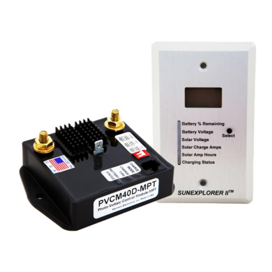
- Page 1 40Amp Charge Controller Display Kit Part#PVCM40D-MPT & SEDM6-40 SUNEXPLORER II-MPT™ Manufactured by: Atkinson Electronics, Inc.
-
Page 2: Table Of Contents
..................Description ..................Kit Contents ..................PVCM40D-MPT Description of Operation ........SEDM6-40 Description of Operation ........... New Installation Instructions for PVCM40D-MPT ..... Installation Instructions for PVCM40D-MPT ......Installation Tips for PVCM40D-MPT ..........Battery Type Selection ..............Power Up Initialization Routine ........... -
Page 3: Diagrams
Features PVCM40D SEDM6-40 www.atkinsonelectronics.com Circuit Board Division 800.261.3602 Revised 05/19... -
Page 4: Description
Solar Voltage Adjust P2: Displays solar voltage adjustment potentiometer. Set during step 3 of SEDM6-40 installation RJ-45 Jack: Power and signal connection point to PVCM40D-MPT charge controller module. Requires Cat-5 patch cable. Cable Error LED: Lights when a crossover cable is connected. -
Page 5: Kit Contents
PVCM40D-MPT PVCM40D-MPT Description of Operation The PVCM40D-MPT, micro-processor based, solar 5 stage charge controller connects PV panels to 12VDC storage batteries. PVCM40D-MPT performs 5 basic functions: 1. Monitors solar panels to know if it has enough solar voltage to start charging the battery(s), and when to adjust the PWM charge rates based on solar conditions. -
Page 6: Sedm6-40 Description Of Operation
Amp hour accumulator, force the PVCM40D-MPT into a bulk charge routine to top off the battery voltage, lock display or current setting, or activate scroll mode (see page 15). The SEDM6-40 will automatically switch back to the battery percent remaining display setting after 4 minutes unless the display setting lock is activated. -
Page 7: New Installation Instructions For Pvcm40D-Mpt
New Installation Instructions for PVCM40D-MPT 1. Complete the installation of the solar panels following the solar panel manufacturer’s instructions for panel mounting and wire size based on total wattage of the solar panels and the distance between panels and batteries. If the distance is less than 15 feet and the total solar panel charge Amps is 40 Amps or less, 8 AWG wire or larger is recommended. -
Page 8: Installation Tips For Pvcm40D-Mpt
If you have flooded lead acid batteries, check the battery fluid level as directed by the battery manufacturer. 4. Install the PVCM40D-MPT in or next to the battery enclosure for the temperature compensation to work properly. -
Page 9: Battery Type Selection
The PVCM40D-MPT’s Lifeline algorithm monitors the battery condition and will perform a conditioning charge, provided the following requirements and conditions are met: MINIMUM Imp of 12 Amps (2x-100 to 160 Watt solar panel), and must complete a full charge cycle. -
Page 10: Power Up Initialization Routine
LEDs red to indicate it is in a soft/ bulk charge. If the soft charge flag was not set, then the charge mode LED will be lit red indicating it is in Battery Type Selection Switch The PVCM40D-MPT’s battery type selection dip switch is located left of the cat5e jack for the SEDM6-40 display module. -
Page 11: Charging Mode Definitions
Charging Mode LED Definitions The Charge Mode LED indicates which of the three main PWM charge stages the controller is in: Bulk charge stage - The LED is lit red Absorption charge stage - The LED blinks red ... -
Page 12: Charging Stage Descriptions
Charging Stage Descriptions Stage 1 - Soft Charge When the batteries are discharged below 10.5VDC, the controller will softly ramp up the charge rate until the battery voltage reaches 10.5VDC at which point it will enter the bulk charge stage. (Battery status LED blinks red, charge type &... -
Page 13: Charging Stage Descriptions Continued
Lifeline batteries can be conditioned if the total Imp. from the solar panels is greater than 10 Amps. The PVCM40D-MPT monitors the solar charge Amps during the Bulk charge stage, if 10+ Amps was detected it sets the 10 Amp Flag. The controller also monitors the battery voltage over a 14 to 21 day period, if the battery voltage drops below 12.1VDC three times in that period or fails to finish the... -
Page 14: Wiring Diagram
Wiring Diagram www.atkinsonelectronics.com Circuit Board Division 800.261.3602 Revised 05/19... -
Page 15: Installation Instructions For Sedm6-40
Installation Instructions for SEDM6-40 1. Complete the installation and test the operation of the PVCM40D-MPT charge control module. 2. Before mounting the SEDM6-40 module, plug in a short cat5e network cable into both, the PVCM40D-MPT controller’s RJ-45 jack and the SEDM6-40 display’s RJ-45 jack and verify that all readings work properly. -
Page 16: Battery Adjustment Pot & Jack Locations
The current display reading will indicate “0" if the controller is not in any of the charging stages. 3. The solar current shunt used in the PVCM40D-MPT is rated for a maximum of 25 Amps. There are other displays and charge controllers in the SUNEXPLORER product line for higher Amperage systems. -
Page 17: User Instructions For Sedm6-40
User Instructions for SEDM6-40 1. The power and signals to the SEDM6-40 display are supplied through the cat5e network cable connecting the SEDM6-40 to a PVCM40D-MPT charge controller. 2. The SEDM6-40 will normally revert back to displaying the continuous battery percent remaining after approximately 4 minutes from any other reading. -
Page 18: Trouble Shooting Tips For Pvcm40D-Mpt
Problem: The battery loads have been left on and the storage battery has discharged below 7VDC. The PVCM40D-MPT is not charging when the load or loads are turned off. Solution: The PVCM40D-PWM needs at least 8VDC from the battery to operate properly. Use an AC battery charger to bring the battery voltage up above 8VDC. -
Page 19: Specifications For Pvcm40D-Mpt
Specifications for PVCM40D-MPT Size & Weight: 3.0 x 4.0 x 1.0 inches, 8 ounces Enclosure: Epoxy potted in PVC plastic Mounting: 2 #10 x .5" L screws (not provided) Power: 7 to 15VDC from storage battery(s) Current Draw: 40Amps @ 25VDC Solar Panels... -
Page 20: Specifications For Sedm6-40
Green LED: Float charge, display indicates “Fch” Red LED: Bulk/ absorption charge “bch/Ach” Manual Boost: Available only during float charging stage. Press and hold Select button while in charging status location will force PVCM40D-MPT into bulk charge mode Temperature: 0 to 50°C www.atkinsonelectronics.com Circuit Board Division 800.261.3602... -
Page 21: Wire Size Recommendation Chart
Wire Size Recommendation Chart www.atkinsonelectronics.com Circuit Board Division 800.261.3602 Revised 05/19... -
Page 22: Cleaning Tips & Template For Sedm6-40
Appendix-A When selecting the correct amperage rating for your in-line circuit breaker, first determine the maximum current output of your solar panel array by adding up the current at maximum Power (Imp) for each panel, then round up to the next standard amperage size. Example: (3) 150watt panels, Imp = 8.5Amps ea. - Page 23 Cleaning Tips Do not spray water or cleaning solution directly to the face plate or LCD of the SEDM6-40. The liquid could run between the face plate and the LCD on to the circuitry on the SEDM6-40 circuit board causing damage to the electronics and WILL VOID THE WARRANTY! Template for the SEDM6-40 www.atkinsonelectronics.com...
-
Page 24: Warnings & Recommendations
Make sure ALL of your connections, from the solar panel to the battery, are coated in dielectric grease Like Ideal Nolax or Permatex www.atkinsonelectronics.com Circuit Board Division 800.261.3602 Revised 05/19... -
Page 25: Limited Warranty
The customer's sole and exclusive remedy and the limit of Atkinson Electronics, Inc.'s liability for any loss whatsoever, shall not exceed the purchase price paid by the customer for the product to which a claim is made.
Need help?
Do you have a question about the PVCM40D-MPT and is the answer not in the manual?
Questions and answers