Table of Contents
Advertisement
Quick Links
This manual and the information contained herein is provided for use as an operation and
maintenance guide. No license or rights to manufacture, reproduce, or sell either the manual or
articles described herein are given. Amron International Diving Supply, Inc. reserves the right to
change specifications without notice.
Instruction Manual
Amron International Diving Supply, Inc.
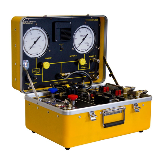
Model 8225-HP & 8225-HP2 AMCOMMAND Il
Two Diver Air Control Systems
S/N______________________
Amron International Diving Supply, Inc.
1380 Aspen Way
Vista, California 92081 U.S.A.
Phone (760) 208-6500 ¥ Fax (760) 599-3857
Email:
Sales@amronintl.com
Website: www.amronintl.com
Copyright © 2005, Amron International, Inc.
Revised December 2011
For
Advertisement
Table of Contents

Related Manuals for Amron AMCOMMAND Il

Summary of Contents for Amron AMCOMMAND Il
- Page 1 This manual and the information contained herein is provided for use as an operation and maintenance guide. No license or rights to manufacture, reproduce, or sell either the manual or articles described herein are given. Amron International Diving Supply, Inc. reserves the right to change specifications without notice.
-
Page 2: Table Of Contents
TABLE OF CONTENTS SECTION Specifications Air Control ........................1.1 Depth Monitoring......................1.2 Communications ......................1.3 Enclosure ........................1.4 General Information Description ........................2.1 Air Control ........................2.2 Depth Monitoring......................2.3 Low Pressure Alarm Module ..................2.4 Communications ......................2.5 Diving Safety and Regulations Diving Safety & Regulations..................3.1 Personnel Requirements....................3.2 Air Supply Requirements ....................3.3 Calibration, Service and Inspection................3.4 Options... - Page 3 TABLE OF CONTENTS SECTION Pre-Dive Procedures Pre-Dive Set-Up ......................7.1 Pre-Dive Check-Out ......................7.2 Pre-Dive Pneumo Test....................7.3 Pre-Dive Communications Test ..................7.4 Connecting Diver Umbilical ...................7.5 Low Pressure Supply ....................7.6 Operating Procedures Low Pressure Breathing Air ..................8.1 High Pressure Breathing Air..................8.2 Pre-Operation Check List....................8.3 Pneumo Readings......................8.4 Diver Communications ....................8.5 2-Wire Operation......................8.6...
- Page 4 TABLE OF CONTENTS SECTION Reference Material Dive Log, U.S. Navy (Chart)..................12.1 Repetitive Dive Worksheet..................12.2 No Decompression Limits ...................12.3 Gauge Pressure for Depth of Seawater & Fresh Water..........12.4 Equivalent Depths of Seawater & Fresh Water............12.5 Drawings Schematic Diagram-Model 2825A-8225 ..............13.1 Parts Identifier, 2832-202....................13.2 Schematic Diagram- 28FDW OPTION................13.3 Schematic and Parts Locator-Model 2324-202............13.4 Parts Locator- Pneumo Front Panel 8225-200 ............13.5...
-
Page 5: Specifications
Check Valve, prevents reverse inlet flow .................2 Input Filter, In Line Pre Regulator ..............50 Micron CGA850 Yoke connections with 6ft. High-pressure hose whips (standard).....2 ***Available with optional 300 Bar DIN Adapters, Amron Part No. SAA5300 High Pressure Regulator, Tescom Outlet Pressure Range..................0-265 PSI High Flow ...................... -
Page 6: Communications
SPECIFICATIONS DEPTH MONITORING (PNEUMO) Pneumo Gauge, 3D Precision Mirrored Scale, 6 Inch ......................2 Range ................. Dual Scale 0-250 FSW/0-76 MSW Divisions........................1 Foot Accuracy .....................0.25% of Full Scale Pneumo Valve Regulating Valve, KEL-F Seat ..................2 Outlet Connection O2 Fitting Chrome Plated Brass ..................2 Low Pressure Alarm Audio Range, 22.5-125 PSI ............ -
Page 7: General Information
GENERAL INFORMATION DESCRIPTION The AMRON AMCOMMAND II Model 8225-HP & 8225-HP2 is a portable self contained two diver high and low pressure air control, communication and depth monitoring (pneumo) system, for surface supplied diving operations. The system is designed to provide a central control point for the supply of breathing air to the divers, monitor the diver’s depth, and provide two way communications... -
Page 8: Low Pressure Alarm Module
100 PSIG. COMMUNICATIONS The diver communication system is based on the field proven AMRON Model 2825. The unit is powered from internal rechargeable gel cell batteries, battery charger provided. Operating time from fully charged battery is approximately 60 hours. Unit can also be operated from an external 12 V DC source, via charger jacks on the front panel. -
Page 9: Diving Safety And Regulations
Each diving supervisor should obtain a copy of these regulations for their own use. Copies of the complete section of Commercial Diving Operations are available from Amron International for a nominal charge. WARNING: DO NOT USE THE AMCOMMAND II FOR THE FOLLOWING Mixed gas diving operations with an oxygen level greater than 40%. -
Page 10: Personnel Requirements
SAFETY & REGULATIONS PERSONNEL REQUIREMENTS Each dive team member shall have the experience or training necessary to perform assigned tasks in a safe and healthful manner. The person operating the AMCOMMAND II must be trained in the proper operating procedures, and emergency operating procedures. It is the responsibility of the designated person in charge of the diving operation to be on-site at all times. -
Page 11: Calibration, Service And Inspection
SAFETY & REGULATIONS CALIBRATION, SERVICE AND INSPECTION 1. Each depth gauge shall be dead weight tested or calibrated against a master reference gauge every 6 months, or if there is a discrepancy greater than two percent (2%) between any two equivalent gauges. -
Page 12: Options
25 feet 1/4" O.D. cable. (Use with Model 2460-28 headset with boom microphone). Model 2822-28 Remote Walk-and-Talk (4-Wire Operation) AMRON headset extension (remote walk and talk), with belt module, jacks for headset, 25 feet 1/4" O.D. cable. (Use with Model 2460-28 headset with boom microphone). -
Page 13: Limited Warranty
INTERNATIONAL DIVING SUPPLY, INC. literature covering this product, for a period of 90 days from date of shipment. Amron's obligation under this warranty is limited to the repair of or replacement, at Amron's option, of defective material. This warranty shall not cover defects, which are the result of misuse, negligence, accident, repair or alterations. -
Page 14: Controls And Connections
Standard 3000 PSI MAX Input All models comes standard with 2 each Amron CGA850 yokes attached to 6-foot long HP hoses. The CGA850 yoke limits the maximum input pressure to 3000 PSI. Optional 4500 PSI MAX Input Installing the 300 Bar DIN Adapters, Amron Part No. - Page 15 CONTROLS & CONNECTIONS AIR CONTROL (Continued) A pre-regulator filter prevents debris from contaminating the regulator. Filter element is 50 micron. High pressure TESCOM regulator(s) reduce pressure of incoming air from high-pressure bottles to a level required by diver’s Hat/Helmet. To increase the diver’s air pressure, turn knob clockwise to desired setting.
- Page 16 CONTROLS & CONNECTIONS AIR CONTROL FRONT PANEL, MODEL 8225-HP...
-
Page 17: Depth Monitoring (Pneumo)
CONTROLS & CONNECTIONS DEPTH MONITORING (PNEUMO) The Pneumo Fathometer section is used to measure the diver’s depth. Pneumo readings are made by pressurizing the diver’s pneumo hose; air is forced through the pneumo hose until all water is displaced. The air is then shut off, and the pressure is read on a high accuracy gauge calibrated in FSW (feet of seawater). - Page 18 CONTROLS & CONNECTIONS PNEUMO FRONT PANEL, MODEL 8225-HP...
-
Page 19: Communications
CONTROLS & CONNECTIONS COMMUNICATIONS Two-way communications with divers. High power folded acoustic horn, provides ample volume for noisy environments. Speaker is mounted in the optimum plane to direct sound to the operator. 1. Speaker, 15 watt folded acoustic horn, with talk-back capability. 2. - Page 20 CONTROLS & CONNECTIONS COMMUNICATOR FRONT PANEL, MODEL 2825A-8225...
-
Page 21: Pre-Dive Procedures
PRE-DIVE PROCEDURES PRE-DIVE SET-UP 1. Place AMCOMMAND II on flat surface that can support the unit. Select a working area which is secure, stable, convenient, and suitable for use during the period of the dive. 2. Open unit and remove both yokes and color coded high pressure hose whips from the storage position. -
Page 22: Pre-Dive Pneumo Test
PRE-DIVE PROCEDURES PRE-DIVE PNEUMO TEST The AMCOMMAND II Pneumo section has gauge protectors to protect the pneumo gauges from over pressurization. However it is good operating practice to use a procedure which will not damage the gauges when operating a system without gauge protectors. Using a standard procedure will permit the operator to use a different system without gauge protectors and operate the system correctly. -
Page 23: Connecting Diver Umbilical
PRE-DIVE PROCEDURES PRE-DIVE TESTING COMMUNICATIONS 1. Always test the communications between the AMCOMMAND II and divers before each dive. Connect the diver’s umbilical to the diver communicator, and the hat/helmet to the umbilical. 2. Turn power to “ON” position. 3. Set “Tenders Volume” at mid scale. While diver is speaking, adjust to a comfortable level. 4. -
Page 24: Operating Procedures
OPERATING PROCEDURES LOW PRESSURE BREATHING AIR (Primary Supply) Low Pressure Compressor (Primary supply), High Pressure (Backup). In this mode of operation the divers breathing air is being supplied by an LP compressor, the HP Supply is use as a back-up supply. -
Page 25: Pre-Operation Check List
OPERATING PROCEDURES HIGH PRESSURE BREATHING AIR (Primary Supply) (cont’d) When planning your dive you must take into consideration the amount of time a given bottle will last, and the number of bottle changes, which will be necessary during the dive. There are two options that can be used to accommodate dives that will have a high consumption of air. -
Page 26: Pneumo Readings
OPERATING PROCEDURES PNEUMO READINGS During the dive the tender shall monitor the diver’s depth, recording the depth and time at depth. The procedure for measuring depth is as follows. Advise the diver that a pneumo reading is to be taken. The diver will place the end of the pneumo hose at the point at which the measurement shall be taken. -
Page 27: Diver Communications
“SIMULCOM”. The diver and tender can talk to each other as you would on a telephone. The same applies to diver to diver conversations. Amron tries to encourage the use of SIMULCOM for superior communications and safety. -
Page 28: 2-Wire Operation
2-wire. Wires should be well fastened to the binding posts and not touching each other. A good method of attachment is to use a dual banana plug (AMRON P/N 14001B). If more than one diver is connected to any microphone (Input), (Diver 1 or Diver 2), those divers on the same two terminals will not be able to Crosstalk. -
Page 29: Diagram, Set-Up Instructions (Figure 3)
OPERATING PROCEDURES DIAGRAM, SET-UP INSTRUCTIONS (Figure 3) -
Page 30: Simulcom (4-Wire) Operation
Turn speaker off to avoid acoustic feedback. Operation with speaker is possible by extending tender’s headset away from the speaker. Use AMRON Model 2822-28 headset extension cable (25 foot). Note: When operating with a standby diver who does not have his hat/helmet on, acoustic feedback (squeal) may occur. -
Page 31: Diagram, Simulcom 4-Wire Connection, Model 2825-8225 (Figure 4)
OPERATING PROCEDURES DIAGRAM, SIMULCOM 4-Wire Connection, Model 2825-8225 (Figure 4) -
Page 32: Simulcom - What, Why And How
OPERATING PROCEDURES SIMULCOM – WHAT, WHY AND HOW ? 8.10 Simulcom is a communications system designed from the “ground-up” to take advantage of the current “state of the art” in semiconductor technology and to provide superior diver hard wire communication. First, the advantages and then an explanation of What, Why, and How. -
Page 33: What Is Simulcom
OPERATING PROCEDURES What is SIMULCOM? 8.11 It is a dual signal path system, with special amplifiers to take care of the problems associated with “Round-Robin”. It allows everyone on the circuit to talk to each other just as if you were on a telephone. - Page 34 OPERATING PROCEDURES WHAT IS SIMULCOM (Continued) 8.11 Doesn’t the same thing happen with “Round-Robin”? No! With “Round-Robin” you split the mic and earphones, but stack all the mics together. The microphones load each other and you are right back where you started. Also, you have another problem - the headset used by the tender usually has 600-ohm earphones and a 50-ohm microphone.
-
Page 35: To Operate And/Or Check-Out Simulcom
OPERATING PROCEDURES TO OPERATE AND/OR CHECK OUT SIMULCOM 8.12 1. Attach hat to umbilical. 2. Attach common-cable to AMCOM II, red banana plug to Diver 1 mic, black banana plug to Diver 1 earphone. 3. Don hat and talk to yourself. If you hear your voice over the earphones, the system is working correctly. -
Page 36: Theory Of Operation
CGA850 SCUBA yokes with bleed valves and color coded hose protectors. Installing the optional 300 Bar DIN Adapter (Amron Part No. SAA5300) will increase the units maximum input pressure limit to 4500 PSI. Simply remove CGA850 yoke nut and yoke from bleeder body, screw on 300 Bar DIN adapter, and tighten with a wrench. - Page 37 THEORY OF OPERATION MECHANICAL (cont’d) Make sure the breathing air source is dry. Scuba cylinders should be filled from a compressor with a good filtration system. The air source for the filling compressor should be from outdoors, and the filling of the tanks should be done on a cold dry day. Place the AMCOMMAND II and the bottles in a warm location.
- Page 38 THEORY OF OPERATION MECHANICAL (cont’d) The pneumo system operates on the bases of a tube extending from the surface of the water to the depth at which the measurement is going to be taken. Air (pressurized) is forced into the tube, until all the water is forced out of the tube.
- Page 39 THEORY OF OPERATION FLOW DIAGRAM, MODEL 8225-HP...
-
Page 40: Electrical
THEORY OF OPERATION ELECTRICAL The diver communicator is fundamentally an intercom, providing two way communication between the diver and the tender or operator. The Model 2825A-8225 can be operated in two different modes; 2-wire requires the use of the push-to-talk switch or Simulcom (4-wire) where voice conversations are the same as a telephone. - Page 41 THEORY OF OPERATION ELECTRICAL (cont’d) AUDIO POWER AMPLIFIERS - U6 and U7 are audio power amplifier integrated circuits connected in a bridge configuration. The output “floats” at approximately 6 volts and should never be connected to ground. The amplified audio “output” signal is directed to divers or tender through relays K1 and K2.
-
Page 42: Functional Block Diagram (2825-8225)
THEORY OF OPERATION FUNCTIONAL BLOCK DIAGRAM, MODEL 2825-8225... -
Page 43: Maintenance
MAINTENANCE REVIEW OF SCHEDULED MAINTENANCE 10.1 The inherent quality of your AMC0MMAND II will provide years of continuous failure-free service, if properly used and maintained. Before and after each dive; Do Functional test, clean and inspect for damage. Every 6 months; calibrate, Functional test, clean and inspect for damage. Every 12 months;... - Page 44 Every 12 months, complete the above tests plus the following: Remove high-pressure valve stems, inspect, clean, lubricate (use Christolube grease, Amron part No. MCG-111-20Z) and install. Check valve seat, threads, packing material for signs of wear or deterioration, replace if necessary.
-
Page 45: Troubleshooting & Repair
TROUBLESHOOTING & REPAIR GENERAL INFORMATION 11.1 Normal shop tools and procedures apply for all repairs. During this section when you are instructed to remove a part or make an adjustment, you are first to remove all pressure from the system, or as a minimum from the section you are working on. Tubing and Tube Fittings -- repair, assembly, and inspection procedures. - Page 46 AIR CONTROL (cont’d) 11.2 HP CHECK VALVES, repairable, Maintenance Kit available from Amron and contain Viton seat and spring. When checking for leaks, be sure to check valve body to end of fitting. HP-FILTER, replaceable element, Maintenance Kit available from Amron and contain element, body gasket, and retainer spring.
-
Page 47: Depth Monitoring
The valves are repairable; they use Teflon seats which can be replaced. A maintenance kit is available from Amron. To replace, remove valve from system. Remove end pieces from valve, remove valve stem packing nut and remove stem. Teflon ball seal and stem packing can now be removed and replaced. -
Page 48: Diver Communications
TROUBLESHOOTING & REPAIR DEPTH MONITORING (cont’d) 11.3 LOW PRESSURE ALARM, To adjust the set point of the low pressure alarm, loosen the locking ring on the pressure switch. Rotate the body of the switch clockwise to increase the set pressure. The set point of the switch is very sensitive to adjustment and requires patience and a steady hand. - Page 49 TROUBLESHOOTING & REPAIR DIVER COMMUNICATIONS (cont’d) 11.4 “Diver 1" Down-link Check Move headset earphone plug from “Headset” (output) to “Microphone” “Diver 1". Talk into headset while pressing the ”Push to Talk" switch. You should be able to talk to yourself with plenty of volume as long as the “Push to Talk”...
- Page 50 TROUBLESHOOTING & REPAIR PROBLEMS AND THEIR POSSIBLE CAUSES 11.5 Unit Does Not Operate Check to see that unit is turned on, (speaker and headset switch). Check that battery condition is ok, (battery condition indicator). Check to see that connections are proper, correct if necessary. Use diver radio field check procedure to determine if problem is within the unit or elsewhere within the communication system.
- Page 51 TROUBLESHOOTING & REPAIR PROBLEMS AND THEIR POSSIBLE CAUSES (cont’d) 11.5 Diver Hears Tender But Tender Cannot Hear Diver, or Volume Is Very Low Check to see if diver is connected to microphone and not earphone. Check to see that volume levels are not turned down.
-
Page 52: Reference Material
REFERENCE MATERIAL DIVING LOG, U.S. NAVY (CHART) 12.1... -
Page 53: Repetitive Dive Worksheet
REFERENCE MATERIAL REPETITIVE DIVE WORKSHEET 12.2... -
Page 54: No Decompression Limits
REFERENCE MATERIAL NO DECOMPRESSION LIMITS 12.3 (NON-REPETITIVE DIVES ONLY) U.S. NAVY DIVING MANUAL (AIR DECOMPRESSION) DEPTH FSW BOTTOM TIME (min) 40....................... 200 50....................... 100 60......................... 60 70......................... 50 80......................... 40 90......................... 30 100....................... 25 110....................... 20 120....................... 15 130....................... 10 140....................... -
Page 55: Gauge Pressure For Depth Of Seawater & Fresh Water
REFERENCE MATERIAL GAUGE PRESSURE FOR DEPTH OF SEAWATER & FRESH WATER 12.4 (GAUGE PRESSURE IN PSI) DEPTH IN FEET FRESH WATER SEAWATER 10..............4.33............. 4.45 20..............8.66............. 8.90 30..............12.99........... 13.35 40..............17.32........... 17.80 50..............21.65........... 22.25 60.. -
Page 56: Equivalent Depths Of Seawater & Fresh Water
REFERENCE MATERIAL EQUIVALENT DEPTHS OF SEAWATER & FRESH WATER 12.5 DEPTH EQUIVALENT DEPTH (FEET OF SEAWATER) (FEET OF FRESH WATER) 10 ......................10.30 20 ......................20.60 30 ......................30.90 40 ......................41.20 50 ......................51.50 60 ......................61.80 70 ......................72.10 80 ...................... -
Page 57: Drawings
DRAWINGS & SCHEMATICS DRAWINGS & SCHEMATICS 13.0 General The following drawings illustrate the electrical and mechanical details of the diver communication unit. The corresponding parts lists for each drawing are detailed in the parts lists section. Revisions As drawings are updated, information about changes is incorporated into a revision sheet. This revision sheet appears in the manual immediately after the drawings. -
Page 58: Schematic Diagram-Model 2825A-8225
DRAWINGS & SCHEMATICS SCHEMATIC DIAGRAM, MODEL 2825A-8225 13.1... -
Page 59: Parts Identifier, 2832-202
DRAWINGS & SCHEMATICS PARTS IDENTIFIER, 2832-202 13.2... -
Page 60: Schematic Diagram- 28Fdw Option
DRAWINGS & SCHEMATICS SCHEMATIC DIAGRAM, 28FDW OPTION 13.3... -
Page 61: Schematic And Parts Locator-Model 2324-202
DRAWINGS & SCHEMATICS SCHEMATIC & PARTS LOCATOR, MODEL 2324-202 13.4... -
Page 62: Parts Locator- Pneumo Front Panel 8225-200
DRAWINGS & SCHEMATICS PARTS LOCATOR, MODEL 8225-200 (Pneumo Front Panel) 13.5... -
Page 63: Parts Locator - Pneumo Back Panel 8225-200
DRAWINGS & SCHEMATICS PARTS LOCATOR, MODEL 8225-200 (Pneumo Back Panel) 13.6... -
Page 64: Parts Locator - Air Control Front Panel 8225-400Hp
DRAWINGS & SCHEMATICS PARTS LOCATOR, MODEL 8225-400HP (Air Control Front Panel) 13.7... -
Page 65: Parts Locator - Air Control Back Panel 8225-400Hp
DRAWINGS & SCHEMATICS PARTS LOCATOR, MODEL 8225-400HP (Air Control Back Panel) 13.8... -
Page 66: Parts Locator - Air Control Front Panel 8225-400Hp2
DRAWINGS & SCHEMATICS PARTS LOCATOR, MODEL 8225-400HP2 (Air Control Front Panel) 13.9... -
Page 67: Parts Locator - Air Control Back Panel 8225-400Hp2
DRAWINGS & SCHEMATICS PARTS LOCATOR, MODEL 8225-400HP2 (Air Control Back Panel) 13.10... -
Page 68: Parts Locator - Diver Communications 2825A-8225-28Fdw
DRAWINGS & SCHEMATICS PARTS LOCATOR, MODEL 2825A-8225-28FDW (Diver Communications) 13.11... - Page 69 DRAWINGS & SCHEMATICS PARTS LOCATOR, MODEL 8000-0201 (Regulator) 13.12...
-
Page 70: Parts List
This will enable you to determine the correct replacement part. If the new part is the recommended replacement part for all units, the old part is not listed in the revision listing. To Order Replacement Parts Contact: Amron International Diving Supply, Inc. 1380 Aspen Way Vista, California, 92081 U.S.A. -
Page 71: Amcomand Ii Air Control System, Model 8225
PARTS LIST AMCOMAND II AIR CONTROL SYSTEM, MODEL 8225-HP 14.1 Reference Part No. Description 1 ........ 8225-200........... Pneumo Panel Assembly, 8225-HP 2 ........ 8225-300........... Case, Air Control & Pneumo System 3 ........ 8225-400HP........A/C Panel Assembly, 8225-HP 4 ........ 8225-500........... HP Yoke/Hose Assembly 5 ........ -
Page 72: 8225-200 Pneumo Panel Assembly
PARTS LIST 8225-200 PNEUMO PANEL ASSEMBLY 14.3 Reference Part No. Description 14 ......1/4-20 NUTSS ........Nut, 1/4-20 S/S 15 ......1/4-20 X1.25HSBHC......Screw 1/4 x 20 x 1.25 S/S 16 ......1/4FWSS .......... Washer, Flat S/S 17 ......1/4LWSS........... Washer, Lock Split 1/4" S/S 10 ...... -
Page 73: 8225-300 Case Assembly
PARTS LIST 8225-300 CASE ASSEMBLY 14.4 Reference Part No. Description N/S ......R419-5961 ........Fiberglass Case 19x14x11.5 N/S ......8200-004 .......... Bracket, Short N/S ......8200-006 .......... Bracket, Long Front N/S ......8225-009........... Bracket, Short w/left notch N/S ......8225-010........... Bracket, Short w/ right notch N/S ...... -
Page 74: 8225-400Hp Air Control Panel Assembly, Model 8225
PARTS LIST 8225-400HP AIR CONTROL PANEL ASSEMBLY, MODEL 8225-HP 14.5 Reference Part No. Description 01 ......8225-001........... Panel, Front Model 8225 02 ......WEBTX-B-4 ........Elbow, Bulkhead Union Brass 03 ......72HP..........HP Hose, ¼” x 72” Long, #4 JIC, 5000 PSI 04 ...... - Page 75 PARTS LIST 8225-400HP AIR CONTROL PANEL ASSEMBLY (Continued) 14.5 Reference Part No. Description 43 ......#8PANELNUT........Panel Nut, #8 Air Control 44 ......CBZ-SS-4-6 ........Elbow, Male 1/4 Tube x 3/8 NPT, S/S 45 ......CUTUS1/4 ........Copper Tubing, Soft, ¼” x .028 Wall 46 ......
- Page 76 PARTS LIST 8225-400HP2 AIR CONTROL PANEL ASSEMBLY (Continued) 14.6 Reference Part No. Description 39 ......CBZ-B-4-6......... Elbow, Male 1/4 Tube x 3/8 NPT, Brass 40 ......CBZ-B-4-4......... Elbow, Male 1/4 Tube x ¼ MNPT, Brass 41 ......CBZ-B-6-6......... Elbow, Male 3/8 Tube x 3/8 MNPT, Brass 42 ......
-
Page 77: 8225-500 Yoke/Hose Assembly
PARTS LIST 8225-500 YOKE/HOSE ASSEMBLY 14.7 Reference Part No. Description N/S ......72HP..........Hose Assembly, 72" HP (5000) N/S ......FTX-B-4-4 ........Male Connector, #4 JIC x ¼ MNPT N/S ......9913-02 ..........Yoke & Bleeder Assembly N/S ......RP75-BLUE ........Hose Protector, Blue N/S ...... -
Page 78: 2825A-8225-400M Front Panel Assembly
PARTS LIST 2825A-8225-400M FRONT PANEL ASSEMBLY 14.9 Reference Part No. Description 01 ......8225A-003 ........Panel, Front Amcom II 02 ......PBSWITCH ........Switch, Push Button SPST (mom) 03 ......7580K6 ..........Switch, Toggle SPST 04 ......P16NP-10K........Potentiometer, 10K ohms with knobs 05 ...... -
Page 79: 2405-28 Microphone, Push To Talk
PARTS LIST 2405-28 MICROPHONE, Push to Talk 14.10 Reference Part No. Description N/S ......2405-28..........Microphone, Hand Held PTT N/S ......14001B ..........Jack, Banana Dual Black N/S ......14001Y ..........Jack, Banana Dual Yellow N/S ......1772..........Cable, Microphone N/S ...... -
Page 80: Recommended Spare Parts
PARTS LIST RECOMMENDED SPARE PARTS 14.12 Reference Part Number Description Qty. 01 ......802045.......Repair Kit, for P/N 4M-C4L-1/3-SS......2 02 ......802065-4....Repair Kit, for P/N 6M-C6L-1-B ........ 2 03 ......822188-SS....Repair Kit, for P/N 4FV6AKVSS-B2500-KRY, ..............4FV6AKVSS-R2500-KRY, ..............4FV6LKVSS-W2500-KRY ........2 04 ...... -
Page 81: Repair & Calibration Log
REPAIR & CALIBRATION LOG REPAIR AND MAINTENANCE LOG 15.1 Model: 8225-HP(2) Serial Number: Date unit was placed in service: Date of Service Description of Service Service By... -
Page 82: Gauge Calibration Log
REPAIR & CALIBRATION LOG GAUGE CALIBRATION LOG 15.2 Gauge Model: 25545-23B11-HDP Serial Number: Date unit was placed in service: Calibration Date Serial Number Comments Calibrated By...
Need help?
Do you have a question about the AMCOMMAND Il and is the answer not in the manual?
Questions and answers