Table of Contents
Advertisement
Advertisement
Table of Contents

Related Manuals for VALCO MELTON DD-1

Summary of Contents for VALCO MELTON DD-1
- Page 1 DD-1 PUMP MANUAL DD-1 PUMP MANUAL DD-1 PUMP MANUAL DD-1 PUMP MANUAL DD-1 PUMP MANUAL For Pumps Built after 09/2006 For Pumps Built after 09/2006 For Pumps Built after 09/2006 For Pumps Built after 09/2006 For Pumps Built after 09/2006...
- Page 2 © Valco Cincinnati, Inc. All Rights Reserved. This manual is furnished with DD-1 pumps built after 09/2006 and may be used or copied only in accordance with the terms of purchase. No part of this manual may be reproduced, stored in a retrieval system, or transmitted, in any form or by any means, electronic, mechanical, recording, or otherwise, without the prior written permission of Valco Cincinnati, Inc.
- Page 3 Declaration of Conformity Declaration of Conformity Declaration of Conformity Declaration of Conformity Declaration of Conformity (According to EN 45014) M an ufacturer: V alco Melton A div ision of V alco C incin nati, Inco rporated 4 11 C ircle Free wa y Driv e C incin nati, OH 452 46 U SA Au tho rized Re pres enta tiv es in...
-
Page 4: Table Of Contents
Section 3 - Wiring Guidelines ........3-1 Routing Low-Voltage Leads ..............3-1 Connecting the Electrical Power ............... 3-1 Section 4 - Basic Features..........4-1 DD-1 Pump Assembly (pumps built after 09/2006) ........4-1 PCB Assembly ................... 4-2 Light Sequence................... 4-3 Section 5 - Installation ............ 5-1 Power Requirements ................. - Page 5 Table of Contents MS013 - DD-1 Pump Manual (built after 9/06) Installing the Filter/Regulator Assembly ..........5-9 Adjusting the Reed Switches (Single Inlet/Outlet Pumps) ....5-10 Adjusting the Reed Switches (Dual Inlet/Outlet Pumps) ....... 5-11 Reversing-Control Wiring Diagram ............5-12 Wiring the Control Box Assembly to the Valves ........
- Page 6 MS013 - DD-1 Pump Manual (built after 9/06) Table of Contents Seal Kit (561xx173) for Stainless Steel Check Valves, Teflon Diaphragms ..............10-10 Pump Support Equipment ..............10-11 Pump Support Equipment Kit (560xx768) ........ 10-11 Pump Support Equipment Kit (560xx806) ........ 10-11 Pump Support Equipment Kit - Suction Tube With Check Valve (561xx078) ..........
-
Page 7: Section 1 - Introduction
The DD-1 pump can be ordered with one or two inlet ports and two discharge ports. Each diaphragm chamber is a single-acting pump. Because of its electronic reversing control, the DD-1 has the unique advantage over any other dual, single-acting diaphragm pump. -
Page 8: Section 2 - Safety And Use
SECTION 2 - SAFETY AND USE SECTION 2 - SAFETY AND USE SECTION 2 - SAFETY AND USE SECTION 2 - SAFETY AND USE SECTION 2 - SAFETY AND USE WARNING! WARNING! WARNING! WARNING! WARNING! Read and follow all safety precautions, warnings, Read cautions, and other recommendations in this manual. - Page 9 Section 2 - Safety Information MS013 - DD-1 Pump Manual (built after 9/06) This symbol indicates the need to Unplug/Disconnect All Power Unplug/Disconnect All Power Unplug/Disconnect All Power Unplug/Disconnect All Power Unplug/Disconnect All Power Symbols - Continued Sources Sources Sources...
-
Page 10: Owner Responsibilities
MS013 - DD-1 Pump Manual (built after 9/06) Section 2 - Safety Information The owner of the equipment is under obligation to manage all safety Owner information. Some examples include: Responsibilities • Examine all safety materials and documents as well as... -
Page 11: Limitations Of Use
Valco Melton Representative before handling the equipment. Valco Melton hot melt units, cold glue units, controllers, inspection systems Installation/ and all related accessories have the following universal safety precautions (this is not intended to be an exhaustive list;... -
Page 12: Shut Down Safety Information
MS013 - DD-1 Pump Manual (built after 9/06) Section 2 - Safety Information Valco Melton hot melt units, cold glue units, controllers, inspection systems Shut Down and all related accessories have the following universal safety precautions (this is not intended to be an exhaustive list; follow all instructions and safety... -
Page 13: Hot-Melt-Specific, General Safety Information
Section 2 - Safety Information MS013 - DD-1 Pump Manual (built after 9/06) Valco Melton hot melt units have the following universal safety precautions in in in in in Hot-Melt- addition to all other universal precautions previously mentioned addition to all other universal precautions previously mentioned... -
Page 14: What To Do If Contact With Hot Adhesive Occurs
MS013 - DD-1 Pump Manual (built after 9/06) Section 2 - Safety Information If hot adhesive comes in contact with the skin, , , , , do the following: What to Do if Contact WARNING! WARNING! WARNING! Do not attempt to remove heated hot melt adhesive from... -
Page 15: What To Do If Adhesive-Related Fire Or Explosion Occurs
Section 2 - Safety Information MS013 - DD-1 Pump Manual (built after 9/06) During the heating and melting process, the surface of the adhesive will be exposed to air. The mixture of polymer fumes and air can catch fire if the hot What to Do if melt is overheated. -
Page 16: Hose Safety Information
MS013 - DD-1 Pump Manual (built after 9/06) Section 2 - Safety Information Hose Safety Do not Do not Do not use bindings, wire ties, or unapproved Do not Do not Information fasteners around the hoses. Do use approved wrapping (P/N 775xx827), making sure the wrapping is slightly snug but not tight. -
Page 17: Diaphragm Pump/Toxic Fluids Safety
Section 2 - Safety Information MS013 - DD-1 Pump Manual (built after 9/06) Hose Safety Information - Do not Do not Do not Do not Do not allow hoses to rub against Continued objects or to come into contact with sharp edges or points. -
Page 18: Section 3 - Wiring Guidelines
SECTION 3 - WIRING GUIDELINES SECTION 3 - WIRING GUIDELINES SECTION 3 - WIRING GUIDELINES SECTION 3 - WIRING GUIDELINES SECTION 3 - WIRING GUIDELINES Warning! Warning! Warning! Warning! Warning! Failure to observe could result in personal injury, death, Routing Low- or damage to equipment. -
Page 19: Section 4 - Basic Features
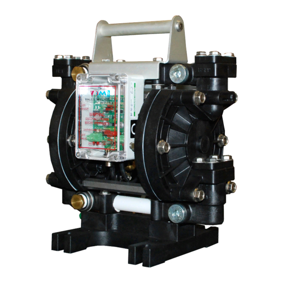
DD-1 Pump Assembly (pumps built after 09/2006) Air Filter/Regulator Assembly DD-1 Pump Control Box Fluid Filter Assembly Air Purge Valve Assembly Filter Bracket Discharge Hose Suction Hose Figure 4-1 - DD-1 Pump Assembly (built 09/2006 and later) Valco Cincinnati, Inc. -
Page 20: Pcb Assembly
Section 4 - Basic Features MS013 - DD-1 Pump Manual (built after 9/06) The Control Box contains the PCB Assembly. Assembly Yellow Reed LED (left) This light comes on when the left reed switch is operating. Yellow Reed LED (right) (Activated by presence of magnet.) -
Page 21: Light Sequence
MS013 - DD-1 Pump Manual (built after 9/06) Section 4 - Basic Features Figure 4-3 illustrates the light sequence that occurs during the pump cycle. Light Sequence The right three-way valve is The right reed switch senses energized, and the magnet moves the magnet and switches power towards the right reed switch. -
Page 22: Section 5 - Installation
SECTION 5 - INSTALLATION SECTION 5 - INSTALLATION SECTION 5 - INSTALLATION SECTION 5 - INSTALLATION SECTION 5 - INSTALLATION An optional remote transformer is available. This transformer requires 100/ Power 120 VAC, 200/240VAC, or 100/200VAC, 1-amp maximum, single-phase power supply with ground, depending on the country where the pump is Requirements installed. -
Page 23: Transformer Wiring
Section 5 - Installation MS013 - DD-1 Pump Manual (built after 9/06) Transformer Wiring See Parts List for additional information. Requirements The pump requires filtered and regulated shop air; 100 psi (8 bar) maximum. Typical Materials required for a central pumping system: •... -
Page 24: Typical Central Pumping System
MS013 - DD-1 Pump Manual (built after 9/06) Section 5 - Installation Typical Central Pumping System - Continued Lateral Line Lateral Line 1.5-2" (38-51 mm) 1.5-2" (38-51 mm) Drop Line Feed Line Drop Line .5-.75" (12-19 mm) 1.5-2" (38-51 mm) .5-.75"... -
Page 25: Installing The Pump
Section 5 - Installation MS013 - DD-1 Pump Manual (built after 9/06) Installation of the DD-1 pump will depend upon the fluid you are using and Installing the your particular application requirements. To install the DD-1 pump, follow these steps: Pump Bolt the pump to a suitable mounting structure. - Page 26 MS013 - DD-1 Pump Manual (built after 9/06) Section 5 - Installation Installing the Pump - Continued Wall-Mounted Diaphragm Pump 55-Gallon Adhesive Drum Figure 5-3 - Wall Mounted Pump Installation Valco Cincinnati, Inc.
- Page 27 Section 5 - Installation MS013 - DD-1 Pump Manual (built after 9/06) Installing the Pump - Continued Figure 5-4 - Drum Mounted Pump Installation Valco Cincinnati, Inc.
-
Page 28: Installing The Single Inlet/Outlet Pump
MS013 - DD-1 Pump Manual (built after 9/06) Section 5 - Installation To install a single inlet/outlet pump (Figure 5-5), follow these steps: Installing the Connect the suction hose to the lower Single 1/2" NPT orifice on the rear face of the pump. -
Page 29: Installing The Dual Inlet/Outlet Pump
Follow the steps for installing a single inlet/outlet pump to connect Dual the fittings and hoses. Inlet/Outlet All DD-1 pumps are set up for suction at the bottom ports and for discharge at the top ports Pump (front or rear). -
Page 30: Installing The Filter/Regulator Assembly
MS013 - DD-1 Pump Manual (built after 9/06) Section 5 - Installation To install the filter/regulator assembly, follow these steps: Installing the The glue supply lines must run from the Filter/ shutoff valve to the fluid pressure regulator. Regulator Install the small in-line glue filter (Figure 5-7) between the... - Page 31 Section 5 - Installation MS013 - DD-1 Pump Manual (built after 9/06) Installing the Filter/Regulator Assembly - Continued 1/4" (6 mm) 1.75" diameter hole (44 mm) 2-3/8" (60 mm) (2 places) 1-9/16" 7/8" (22 mm) (40 mm) 25/64" (10 mm) diameter hole 9/32"...
-
Page 32: Adjusting The Reed Switches (Single Inlet/Outlet Pumps)
MS013 - DD-1 Pump Manual (built after 9/06) Section 5 - Installation 10. Move both switches toward the center another 1/8" (3 mm). Adjusting the Reed Switches (Single Inlet/Outlet Pumps) - Continued 11. Visually check the pump by removing the guard and observing the shaft as the pump cycles. -
Page 33: Reversing-Control Wiring Diagram
Section 5 - Installation MS013 - DD-1 Pump Manual (built after 9/06) Reversing- Reed Switches wires are permanently soldered to their connections. Control Wiring Diagram Air Valve Control Board Assembly Reed Switch (SW2) Reed Switch (SW1) Adjustment Slide Adjustment Slide... -
Page 34: Wiring The Control Box Assembly To The Valves
MS013 - DD-1 Pump Manual (built after 9/06) Section 5 - Installation 3-Way Air Valve (Right) Wiring the Activated by the left reed switch. Moves magnet toward the right reed switch. Control Box Terminal 1 to Item A Assembly to... -
Page 35: Section 6 - Operation
SECTION 6 - OPERATION SECTION 6 - OPERATION SECTION 6 - OPERATION SECTION 6 - OPERATION SECTION 6 - OPERATION WARNING! WARNING! WARNING! WARNING! WARNING! To avoid potential accidents, Valco Cincinnati recommends Operating the that the air supply and electric power be disconnected from the pump when your system is not in operation or is left Pump unsupervised for an extended period of time. -
Page 36: Section 7 - Maintenance
SECTION 7 - MAINTENANCE SECTION 7 - MAINTENANCE SECTION 7 - MAINTENANCE SECTION 7 - MAINTENANCE SECTION 7 - MAINTENANCE Caution! Caution! Caution! Caution! Caution! Never hose or steam-clean the unit. If the surrounding area Cleaning the is cleaned in this manner, protect the unit by covering it with plastic or other waterproof material. -
Page 37: Disassembly Procedure (Dd-1 Pumps Manufactured After September 2006)
Section 7 - Maintenance MS013 - DD-1 Pump Manual (built after 9/06) To disassemble DD-1 pumps manufactured Disassembly before September 2006, please see manual MS005. Procedure (DD-1 Pumps To disassemble pumps manufactured after September 2006, follow these Manufactured steps: after Follow the shutdown procedure on page 7-1. -
Page 38: Disassembly Procedure For Check Valves
MS013 - DD-1 Pump Manual (built after 9/06) Section 7 - Maintenance Teflon check valves (ball type) are standard on the DD-1 pump. Teflon is Disassembly used with fluid viscosity of 1-2500 cps. Stainless check-balls, for viscosity Procedure for greater than 2500 cps, are also available . - Page 39 Section 7 - Maintenance MS013 - DD-1 Pump Manual (built after 9/06) Cleanup Procedure for Recirculating/Ink Pumps - O-ring Continued Corner Check-Ball Figure 7-1 - Replace Check-Balls and/or Corners Gravity Feed to Reservoir 3/4-inch I.D. Hose Ink Collector Tray 3/4-inch...
-
Page 40: Cleaning The In-Line Filter
MS013 - DD-1 Pump Manual (built after 9/06) Section 7 - Maintenance The in-line filter should be cleaned regularly. To clean the in-line filter, follow Cleaning the these steps: In-Line Filter Remove the filter cap. Remove the filter screen. Clean the filter screen with either a mild vinegar-and-water solution or a propane torch. -
Page 41: Section 8 - Troubleshooting
SECTION 8 - TROUBLESHOOTING SECTION 8 - TROUBLESHOOTING SECTION 8 - TROUBLESHOOTING SECTION 8 - TROUBLESHOOTING SECTION 8 - TROUBLESHOOTING Problem Possible Cause Possible Solution Pump will not start 1a. Electrical: -Power input LED out 1a. Check line fuse. Check plant power supply. Replace PC board/transformer assembly. - Page 42 Section 8 - Troubleshooting MS013 - DD-1 Pump Manual (built after 9/06) Problem Possible Cause Possible Solution 3. Pump runs without Suction leakage Test and repair suction components. flow. Blocked suction line Check and clean suction strainer if used. Check installation.
-
Page 43: Section 9 - Specifications
24 VDC, 1-amp; other power source: 24 VAC, 1-amp Air Requirements: Filtered and regulated shop air, 100 psi maximum 1/2” NPT Port on Left Side 1/2” BSP Port on Right Side Figure 9-1 - DD-1 Inlet and Outlet Ports Valco Cincinnati, Inc. -
Page 44: Flow Rate
Section 9 - Specifications MS013 - DD-1 Pump Manual (built after 9/06) To determine the discharge pressure and flow rate, do the following: Flow Rate Select the desired discharge pressure for pump operation. For this example, we will use 50 psi (located on the “Discharge Pressure”... -
Page 45: Air Consumption
MS013 - DD-1 Pump Manual (built after 9/06) Section 9 - Specifications To determine air consumption, do the following: Air Consumption Using the 50 psi found in Step 1 of the previous Flow Rate subsection, project a horizontal line from 50 psi on the “Discharge Pressure”... -
Page 46: Viscosity Correction
Section 9 - Specifications MS013 - DD-1 Pump Manual (built after 9/06) To accurately predict flow according to viscosity, do the following: Viscosity Correction Find the viscosity for the adhesive being used on the “Viscosity” axis. For this example, use 1200 centipoise. -
Page 47: Section 10 - Part Number List
Melton S.L.U. Pol. Industrial Agustinos Spain: calle G, n. 34 31160 Orcoyen, Navarra, Spain Tel: (34) 948-321-580 Fax: (34) 948-326-584 Valco Melton France Valco Melton France Valco Melton France Valco Melton France Valco Melton France Technoparc des Hautes Faventines France:... -
Page 48: Pump Assemblies
DD-1 pump assembly, Teflon diaphragm, stainless steel check valves—562xx051 562xx024 DD-1 transformer assembly—036xx175 Power plug, 16A, 250V—061xx170 DD-1 ink pump assembly, Teflon diaphragm, Teflon check valves, dual outlet— 562xx030 562xx053 Cable assembly, valve, 33-ft.—030xx738 DD-1 ink pump assembly, Teflon diaphragm, Teflon check valves, dual outlet—... -
Page 49: Pump Parts
MS013 - DD-1 Pump Manual (built after 9/06) Section 10 - Part Number List Pump Parts 562xx050.dwg Valco Cincinnati, Inc. 10-3... - Page 50 Section 10 - Part Number List MS013 - DD-1 Pump Manual (built after 9/06) Pump Parts - Continued Item Number Description Part Number HANDLE DD-1 PUMP 583XX633 SCREW 798XX620 NUT BAR DD-1 PUMP 884XX430 HEX HEAD PIPE PLUG 797XX040 SCREW,HEX FLANGE...
- Page 51 MS013 - DD-1 Pump Manual (built after 9/06) Section 10 - Part Number List Pump Parts - Continued Item Number Description Part Number SCREW 798XX429 SUPPORT BAR 580XX633 LINK 788XX499 SWIVEL FTG. - FEMALE 750XX001 STREET ELBOW 797XX005 SCREW 798XX085 MAGNET &...
-
Page 52: 24Vdc Air Valve Assembly (411Xx434)
Section 10 - Part Number List MS013 - DD-1 Pump Manual (built after 9/06) 24VDC Air Valve Assembly (411xx434) Output Input Exhaust Push insulation tubing over the wires and up to the rubber grommet inside the valves’s housing. Strip the end of each wire 0.16” (4 mm) from the end and solder. -
Page 53: Diaphragm Shaft Assemblies
MS013 - DD-1 Pump Manual (built after 9/06) Section 10 - Part Number List Diaphragm Shaft Assemblies Teflon/Stainless Steel (560xx554) Item Number Part Number Description 791xx045 Shaft 560xx556 Diaphragm plate 560xx625 Diaphragm 560xx555 Diaphragm plate 798xx919 Diaphragm retainer screw EPDM/Stainless Steel... -
Page 54: Pump Seal Kits
Section 10 - Part Number List MS013 - DD-1 Pump Manual (built after 9/06) Pump Seal Kits Seal Kit (561xx174) for Teflon Check Valves, EPDM Diaphragms Seal Kit 561xx174 is used to rebuild pump 562xx052. Part Number Description Quantity 745xx820... -
Page 55: Seal Kit (561Xx171) For Teflon Check Valves; Solenoid And Fuse Pack Included
MS013 - DD-1 Pump Manual (built after 9/06) Section 10 - Part Number List Seal Kit (561xx171) for Teflon Check Valves; Solenoid and Fuse Pack Included Seal Kit 561xx171 is used to rebuild pumps 562xx050 and 562xx053. Part Number Description... -
Page 56: Seal Kit (561Xx173) For Stainless Steel Check Valves, Teflon Diaphragms
Section 10 - Part Number List MS013 - DD-1 Pump Manual (built after 9/06) Seal Kit (561xx173) for Stainless Steel Check Valves, Teflon Diaphragms Seal Kit 561xx173 is used to rebuild pump 562xx051. Part Number Description Quantity 745xx820 Shaft seal, Viton... -
Page 57: Pump Support Equipment
MS013 - DD-1 Pump Manual (built after 9/06) Section 10 - Part Number List Pump Support Equipment Pump Support Equipment Kit (560xx768) Part Number Description Quantity 580xx941 Support bracket, filter 594xx113 Air filter regulator assembly 703xx334 Ball valve 755xx012 Input air hose 799xx104 ½-inch x ½... -
Page 58: Pump Support Equipment Kit - Suction Tube With Check Valve (561Xx078)
Section 10 - Part Number List MS013 - DD-1 Pump Manual (built after 9/06) Pump Support Equipment Kit - Suction Tube With Check Valve (561xx078) Part Number Description Quantity 794xx538 Tube support bushing 794xx536 Bushing 2 NPT x 1 NPT 797xx821 Adapter, barb, ½... -
Page 59: Suction Tube Conversion Kits
MS013 - DD-1 Pump Manual (built after 9/06) Section 10 - Part Number List Suction Tube Conversion Kits 560xx636 Valco Cincinnati, Inc. 10-13... -
Page 60: Suction Tube Conversion Kit - With Check Valve (561Xx079)
Section 10 - Part Number List MS013 - DD-1 Pump Manual (built after 9/06) Suction Tube Conversion Kit - With Check Valve (561xx079) Part Number Description Quantity 794xx538 Tube support bushing 794xx536 Bushing 2 NPT x 1 NPT 560xx075 Drum tube assembly with check valve... -
Page 61: Power Supply Cables
MS013 - DD-1 Pump Manual (built after 9/06) Section 10 - Part Number List Power Supply Cables Part Number Description 030xx594 13-foot (4.0 m) connector cable, M12 5-pin connector both ends 030xx604 20-foot (6.0 m) (field-wireable) 030xx604 20-foot (6.0 m) connector cable (field-wireable) 030xx596 33-foot (10.0 m) connector cable (field-wireable) -
Page 62: Transformer (036Xx175)
Section 10 - Part Number List MS013 - DD-1 Pump Manual (built after 9/06) Transformer (036xx175) 10-16 Valco Cincinnati, Inc. - Page 63 MS013 - DD-1 Pump Manual (built after 9/06) Section 10 - Part Number List Transformer (036xx175) - Continued Item Description Part Number Quantity Enclosure; Trans. Assy. 025XX664 Plate; Mounting 025XX665 Shcs M4 X 25 Ss 784XX108 *Transformer; Dual, 24v 550XX089...
-
Page 64: Control Box
Pail lid for DD-1 pump with LLD 560xx813 Pail lid for DD-1 pump 560xx589 Wall mount bracket 594xx113 Air filter for DD-1 pump, 0-160 psi, 1 outlet 036xx175 Remote transformer (optional) 755xx012 10-ft. air supply hose with disconnect 10-18 Valco Cincinnati, Inc. -
Page 65: Section 11 - Warranty
(3) and Related years from the date of shipment by Valco Cincinnati. Equipment Valco Cincinnati is not responsible for the following: DD-1 Pump • Overpressurization Exclusions • Modification of parts • Using damaged or excessively worn parts •... -
Page 66: Section 12 - Service
SECTION 12 - SERVICE SECTION 12 - SERVICE SECTION 12 - SERVICE If you experience a problem with the DD-1 pump, consult the Troubleshooting Section. If a problem with your system persists, contact a Valco Cincinnati Technical Support representative. If your need is urgent, we encourage you to contact our corporate office in Cincinnati, Ohio, U.S.A.
Need help?
Do you have a question about the DD-1 and is the answer not in the manual?
Questions and answers