Advertisement
Quick Links
Advertisement

Subscribe to Our Youtube Channel
Related Manuals for KEY RK-2001TW4


Summary of Contents for KEY RK-2001TW4
- Page 1 OPERATING MANUAL RK-2001TW4 SOLID FUEL FIRED BOILER CONTROLLER Version C112...
- Page 3 1. Application. Controller RK-2001TW4 is intended for temperature control in the solid fuel fired water boilers. The boiler temperature is maintained at the level programmed by the user with blower rotational speed control. The temperature of the boiler water is monitored continuously by the regulator and shown on the display as well as the unit controls the central heating circulation pump.
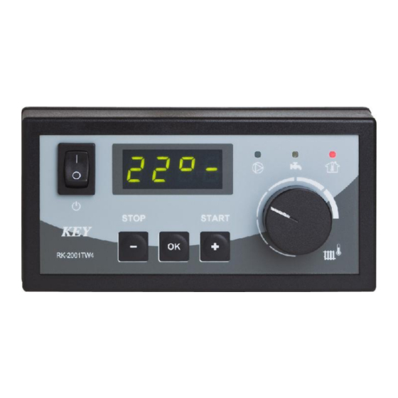
- Page 4 Picture 1. Front panel of the RK-2001TW4 controller. The basic operation of the regulator depends on setting the desired temperature with the thermostat knob; the remaining functions are carried out according to the programmed parameters of the service mode. The change of thermostat parameters is shown on the display for a few seconds, e.g.
- Page 5 Table 1. List of the user’s parameters. Prod. Display Parameter Min Max Jump settings C 45 Programmed boiler temperature L45 H85 1°C co C Central heating pump work while C (pump is off when ‘-‘) cu u Heating up 50° Temperature of water in the domestic hot water tank Exiting the user’s mode 4.1.
- Page 6 the OK button. Then the regulator enables the user to select (<,>) the next parameter. If it is not our intention to change the parameter value with the < or > buttons, then select [End ] and press the OK button or wait about 1 minute – the regulator will leave the service mode and the temperature of the boiler water will be shown.
- Page 7 5.1. Parameters of blower work. Blower work capacity [Π100] – is the value of blower work capacity. When the „Πr” parameter is set to ‘0-10’, then this is the maximum capacity that can be obtained while automatic regulation. Minimum capacity of the blower [n 40] – is the minimum value of capacity at which the blower can work while the automatic regulation of rotational speed and gradual increase of rotations during ignition are on.
- Page 8 5.2. Central heating circulation pump working parameters. Temperature of central heating pump turn-on. [P 42] – is the value of the boiler water temperature at which the central heating circulation pump is turned on. The pump works regardless of the regulation process. Additionally, it is turned on in case of boiler overheating.
- Page 9 Boiler maximum temperature [H 85] – is the maximum value of temperature that can be set with the thermostat knob. Hysteresis of boiler temperature [h 2] – determines by how many degrees the temperature of the boiler water must be decreased from the programmed with thermostat so that the blower should be turned on.
- Page 10 option is useful in the heating systems where the solid fuel fired boiler is included in order to decrease the costs of heating. After the fuel demand alarm has been cancelled with the STOP button, the additional boiler is turned off again and the work of the regulator is resumed.
- Page 11 6. Additional options. To make the user feel more comfortable in the heated rooms, the regulator has been equipped with the input that enables to connect any household thermostat provided with a contact output. If the temperature in the room is lower than the desired one, the turning on the central heating circulation pump and the household thermostat light indicator will occur which means the temperature programmed with the thermostat knob should be maintained by the boiler.
- Page 12 Boiler temperature adjustment range 30-90°C + 1°C Boiler programmed overheating protection 90-99°C + 1°C Boiler equipment overheating protection >95°C + 1°C Pump turn-on temperature 30-70°C + 1°C Total outputs rating max 2A/230V Picture 2. Schematics of connecting the RK-2001TW4 unit.
- Page 13 Picture 3. Schematics of connecting the UM-1 unit.
-
Page 15: Declaration Of Conformity
DECLARATION OF CONFORMITY Manufacturer:Przedsiębiorstwo Wielobranżowe KEY 11-200 Bartoszyce, ul. Bohaterów Warszawy 67 hereby declares that the product: RK-2001TW4 Controller is in conformity with provisions of the following directives: 73/23/EWG i 93/68/EWG (LVD 73/23/EEC + 93/68/EEC), as superseded by Directive 2006/95/WE (EC Directive 2006/95/EEC);... - Page 16 Producent: P.W. KEY 11-200 Bartoszyce, ul. Bohaterów Warszawy 67 tel. (89) 763 50 50, fax. (89) 763 50 51 www.pwkey.pl e-mail: pwkey@onet.pl...
Need help?
Do you have a question about the RK-2001TW4 and is the answer not in the manual?
Questions and answers