
Related Manuals for KAEL VARko-106-TFT


Summary of Contents for KAEL VARko-106-TFT
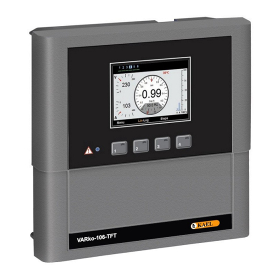
- Page 1 VARko-106-TFT 6 Steps Reactive Power Control Relay √ Banks √ Markets √ Oil Stations √ Schools √ Workshops √ Hotels www.kael.com.tr KAEL Mühendislik Elektronik Tic. ve San. Ltd.Şti.
-
Page 2: Specifications
Specifications √ Easy to use with English menu √ Advanced software √ Easy to commissioning √ Color LCD screen ( 320 x 240 pixel 2.4” ) √ Enough number of steps needed ( 6 steps ) √ Quickly and accurately detection power of capacitors √... - Page 3 12- The alerts and the warnings above are just for your security. In case of not applied, KAEL Elektronik Ltd. or its seller is not responsible for undesirable conditions.
-
Page 4: Step Indicator
A step indicator made by symbols that can be easily realized by the user, is located on the upper part of the screen of VARko-106-TFT. No matter which part of the user in, this panel is always located on the top of the screen. - Page 5 Commisioning 1. Step : Number of Steps 1 2 3 4 5 6 1 2 3 4 5 6 Enter number of step Enter number of step When commissioning the first time, start values are loaded into the device. Then it requires to seconds seconds enter the number of steps.
-
Page 6: Main Screen
Connections Current direction L3 (T) L2 (S) X/5A L1 (R) VARko-106-TFT (Fan output) (Alarm output) Fuse compatible to the capacitor power 400V AC Main Screen Steps Temperature Voltage Cos Φ (L-L) Total Harmonic Distortion Current Frequency... - Page 7 1. MENU This is the section in which many of the electrical measurements 1 2 3 4 5 6 are monitored and set-up are made. The parameters are MENU accessed by direction keys in the menu, parameters are inserted Target TanΦ - CosΦ ►...
- Page 8 Current Trans. Ratio ( 5..10000 / 5A ) This is the section in which the primary value of current transformers in compensation system, is entered. The value is setup to the required step by using up and down keys starting from the digit where the blue line is.
- Page 9 3 4 5 3 4 5 3 4 5 Kvar Kvar Kvar - 1,000 - 1,000 - 1,000 Steps Step - 1,500 - 1,500 - 1,500 Delete ? Delete ? - 2,500 - 2,500 - 2,500 - 5,000 - 5,000 - 5,000 - 5,000 - 5,000...
- Page 10 – HD on Voltage (enable) 1 9 1 1 8 Phase Alarms In case the failure of any harmonics between 3...31 in the phase voltage exceeds the set value during the activation of alert, device warns the user. In this case; - You should install harmonic filter to protect your devices.
- Page 11 Alarm Setting Values 1 9 2 This is the section in which the alarm setup values are entered. Over Voltage (420 – 500V) 1 9 2 1 This is the section in which the value of over voltage are entered. You may enter a value between 440 and 500 Volts.
- Page 12 THD Voltage Setting (% 1 – 100) 1 9 2 4 This is the section in which total harmonic distortion value (THDV) are entered for voltage. You may enter a value between 1% and 100%. The value is setup to the required value by using the up and down key starting from the digit where the blue line is.
- Page 13 Fan Settings 1 9 3 This is section in which the setup values of fan inputs are entered. Fan Temperature Value (5 – 85 °C) 1 9 3 1 This is the section in which fan output activation value is entered. You may enter a value between 5 and 85 °C.
- Page 14 Password Settings 1 10 Password Enable/Disable 1 10 1 This is the section in which the use of device is activated or de- 3 4 5 activated with password. Initial password is “0000”. In case the user User Password Status changes the password, old password is valid even if returned to the factory settings.
- Page 15 Factory Defaults 1 12 This is the section which is used to restore factory default values to the device. 3 4 5 SETUP 1 12 Factory Default Values : Delete Step Powers Target TanΦ(cosΦ) : % 0 (1,00) Alarm & Protection Par. Switch on Time : 10 sec Password Settings...
- Page 16 Technical Info Power supply (Operating Voltage) (Un) : (Phase-Phase ) 400Vac Operating Range : (0,9-1,1) x Un Operating Frequency : 50/60 Hz Supply Power Consumption : < 6VA Power Consumption of Measurement Inputs : < 1VA Contact Current : Max.3A/240 Vac : (as the secondary current of the current transformer) 0,01 - 6 Amp AC Display Range...
Need help?
Do you have a question about the VARko-106-TFT and is the answer not in the manual?
Questions and answers