Table of Contents
Advertisement
Quick Links
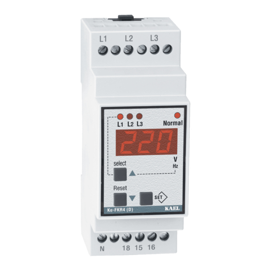
ke-FKR4 (D)
Digital Phase
Failure and
Phase Sequence
Device
General
In three phase systems, it measures
RMS values of AC voltages and system
frequency sensitively. Using up direction
button (Select) phase-neutral voltages and
phase-phase voltages monitor sequentially
ke-FKR4(D) has many features.
Those are;
- Phase Failure
- Phase Sequence
- Over Voltage Protection
- Under Voltage Protection
- Voltage Unbalance (asymmetry)
Protection
- Over Frequency Protection
- Under Frequency Protection
When device is turn on if its adjusted
voltages and frequency in its interval and
if phase sequence is correct relay switch on.
If any of error occurred ( except phase failure
and phase sequence ) at the end of adjusted
time relay switch off its contact. When system
return normal values, at the end of time out
relay switch on.
IMPORTANT: L1 - N is device supply inputs. Thus,the applied L1 – N voltage
must be rated voltage of system .
The measured frequency also must the frequency of the system.
Phase Failure: (u-U)
Before starting system , it controls phase absence then if all phases exits Normal
LED turn on and relay contact switch on. In case of missing of any L1,L2,L3
phases , Normal LED turn off and relay switch off its contact .In this case when
pressing Reset button,
u-U
warn appears on display.
L1
L2
L3
Re
< t-3
V
V
V
,
L1
L2,
L3
V
V
V
L12,
L23,
L13
Phase Sequence Control
Over Voltage Protection
Under Voltage Protection
Unbalanced Voltage
Protection
Over Frequency
Protection
Under Frequency
Protection
Latch Function
TRUE RMS
Display
Function:
L1 L2 L3
V
L1
L1 L2 L3
V
L2
L1 L2 L3
V
L3
L1 L2 L3
V
L12
L1 L2 L3
V
L23
L1 L2 L3
V
L13
Select:(Up direction) when
pressing continuously,
screen displays frequency
of system. When button
release device continue
to show voltage.
t-3
Phase Sequetion: (Seq)
In case of wrong phase order , Normal LED turned off and relay contact is
not switch on. In this case if Reset button pushes
phase order is corrected , Normal LED turned on and out relay switch on.
L1
L1,L2,L3
L1,L3,L2
L2
L3
Re
Voltage Unbalanced: (unb)
The phase-phase voltage unbalance limit can be adjusted between(%5-%20) .
When it exceeds the adjusted limit , the device switched off its out contact
at the end of t-1 delay. In this case when pushing Reset button
appear on the screen. For the returning normal state, asymmetry values
should under % 20 (hysteresis value). In this case at the end of t3 time Normal
LED turned on and output contact switch on. If the phase-phase voltage
unbalance, return adjusted value shorter than t-1 time, output relay does not
release its contact. Hysteresis is %20.
.
Example: Let's say that asymmetry value is set to 15% for a 3 x 380VAC.
In this case, relay contact switch off at (380-(380x0.15))=323 V.
Switch on the contact is performed at 323+(380x15%x20%)= 334V.
(20% is the hysteresis).
(V
- V
)
max
min
% un b =
x 100
380
+ % unb
Hys
V
nom
Hys
- % unb
Level
Re
t-3
Over and Under Voltage : (o-U),(u-U)
Under voltage (u-U) it can adjusted between Umin= (300 – 370 V).
Over voltage
(o-U) it can adjusted between Umax=(390 – 460 V).
If the voltage drops below the adjusted under voltage limit, when
on the screen and device switch off its output contact end of the t-1 time
Normal LED turned on .In this case when pushing Reset button
appear on its screen.
If the voltage exceed the adjusted over voltage limit, Normal LED turned off
and output relay switch off. In this case when pushing Reset button
appers on its screen.
V
Over Voltage
Umax
(o-U)
Normal
Umin
(u-U)
t-1
t-3
Re
LOCKING FUNCTION : (LATCH)
It can be controlled by two parameters. Locking time and Locking counter.
If the number of opening reaches the adjusted locking counter withing the
adjusted locking time then device switch off its contact and locks its
functions until the user pressed Reset button.
If the locking counter is adjusted to
device never locks itself.
L-t : Locking Time ( 001 – 060 min. )
It is well know the frequently occurring faults may damage system. For that
the device when number of faults reaches the adjusted locking number
within this locking time. This way the system is protected and user has
chance to investigate the problem.
L-C : Locking Counter ( oto , 001 – 010 piece )
The number of faults allowed within the period L-t. If number of faults
exceeds this adjusted counter value device locks itself. User must press
Reset button then the fault passes in order to unlock the device.
If L- C is set to oto then this property is disabled.
seq
warn displayed. If
L1,L2,L3
L2,L3
unb
warn
Hys = 380 x (% Asm) x (% 20)
< t-1
t-1
t-3
u-U
shows
u-U
warn
o-U
warn
L1,L2,L3
Normal
Under Voltage
t-1
t-3
oto
then this function is disable and
®
t-1
t
t
Advertisement
Table of Contents

Related Manuals for KAEL ke-FKR4


Summary of Contents for KAEL ke-FKR4
- Page 1 (Select) phase-neutral voltages and < t-1 phase-phase voltages monitor sequentially L1 L2 L3 ke-FKR4(D) has many features. Those are; Over and Under Voltage : (o-U),(u-U) - Phase Failure Under voltage (u-U) it can adjusted between Umin= (300 – 370 V).
- Page 2 Over Frequency be able to set between (o-F) = [(u-F) + 0,4]..70 Hz - If you are having any problem you can contact to KAEL Electronics Co. If required , it can be set only under frequency or only over frequency protection where you can reach address given below.
- Page 3 Connection Scheme 16 18 Select: (up direction) when pushing continuously ,it shows systems frequency its screen. When release button , it is continue to display voltage. Reset: If pushing Reset button while system has any error, device shows alarm codes. If error case although disappeared , then device is not return to normal , latch-function occurred and it makes locked device .
Need help?
Do you have a question about the ke-FKR4 and is the answer not in the manual?
Questions and answers