Advertisement
Quick Links
Advertisement

Related Manuals for Kuhne electronic TR 144 H +40

Summary of Contents for Kuhne electronic TR 144 H +40
- Page 1 Manual DB 6 NT 144 MHz Transverter TR 144 H +40 © 1.2015 DB 6 NT...
- Page 2 Several decades of engineering and production of Transverters result in this new designed high performance Transverter TR 144 H +40. Its outstanding technical data make it usable for many applications. The transverter was originally designed for VHF amateur radio applications, for example high performance contest stations.
- Page 3 TR 144 H +40 Oscillator A temperature-compensated low noise butler oscillator generates the 116 MHz LO signal. A thermostat crystal with a 40 °C precision crystal heater is used. Phase noise of the output signal is -156 dBc/Hz @ 10 kHz. This value is better than that of the HF transceivers.
-
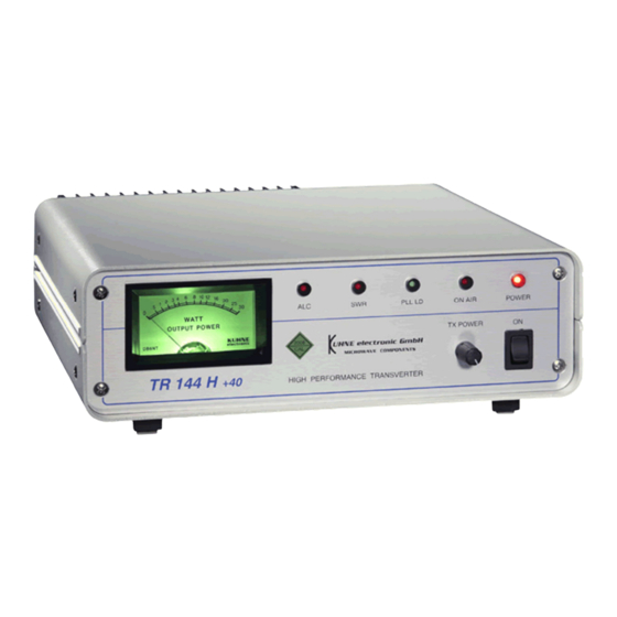
Page 4: Connections And Indicators
TR 144 H +40 Connections and Indicators On / Off switch TX POWER Potentiometer for adjustment of the TX gain POWER On indicator ON AIR Illuminates during transmit operation PLL LD Illuminates as soon as the internal crystal oscillator of the transverter is locked to the external reference frequency. - Page 5 TR 144 H +40 Connections and Indicators Antenna connector 10 Separate receiver input For optional use (see "Setup before first Operation") 11 Transverter output RX OUT to HF transceiver, if two separate IF connectors are used. Transverter input and output RX OUT / TX IN if one common IF connector is used.
-
Page 6: User Controls And Indicators
TR 144 H +40 User controls and Indicators CON SW Switch for connector configuration. (see "Internal Switches CON SW / TX IF SW") TX IF SW Switch for IF amplifier configuration. (siehe "Internal Switches CON SW / TX IF SW") LED - TX IF SW Active when "TX IF SW"... -
Page 7: Connector Wiring
TR 144 H +40 Connector Wiring During transmit mode pin 1 is switched to ground via a Wiring of SUB-D plug-in connector MOSFET (max. 0.4 A). This output signal is time-delayed and can be used to switch an external antenna relay at the antenna. -
Page 8: Setup Before First Operation
TR 144 H +40 Setup before first Operation Connect the control cable. Please follow the description in the handbook of your HF transceiver Connect a suitable antenna or a dummyload (power meter) to the antenna connector. Open the transverter by removing the top cover (4 screws). - Page 9 Interne Schalter / Internal Switches CON SW / TX IF SW Schalter CON SW Mit diesem Schalter werden die ZF-Buchsen des Transverters konfiguriert. Voreinstellung ab Werk - siehe Messprotokoll. CON SW Schalterstellung A Beide ZF-Buchsen des Transverters sind aktiv (getrennte Buchsen für Sendung und Empfang).
- Page 10 Interne Schalter / Internal Switches CON SW / TX IF SW Schaltersetups für gebräuchliche Kurzwellentransceiver. Bei dem Verbinden des verwendeten Kurzwellentransceivers mit demTransverter sind die Betriebshinweise im Handbuch des Kurzwellentransceivers zu beachten. Some internal switch setup examples for well known HF-transceivers. See the instructions in the handbook of the used HF-transceiver how to work with an external transverter.
- Page 11 Informationen zum 10 MHz Referenzeingang der DB6NT-Transverter Es besteht die Möglichkeit den Transverter an ein 10 MHz Frequenznormal (Referenzfrequenz) anzuschließen. Wird eine externe 10 MHz-Quelle angeschlossen, so wird automatisch auf PLL-Betrieb umgeschaltet. Die Frequenzstabilität ist nun von der Referenzfrequenz abhängig. 10 MHz können von hoch stabilen OCXOs, Referenzoszillatoren von Frequenzzählern, Rubidium-Frequenznormalen oder GPS-gesteuerten Referenzquellen eingespeist werden.
- Page 12 TR 144 H +40 Transverter configurations Some examples of transverter configurations Version A: TR 144 H +40 without additional amplifier Version B: TR 144 H +40 with antenna relay and power amplifier preamplifier preamplifier power amplifier Version C: TR 144 H +40 with antenna relay...
- Page 13 TX-cable 13.8V TR 144 H +40 with HF-Transceiver TS 850 When connecting the TS 850 with the transverter all modification instructions in the HF-transceiver manual must be observed. Especially important is the provision of 12 VDC to the drive output which disables the power amplifier. It is suggested to study the DJ 9 BV modification proposal published in DUBUS magazine 2/1992, page 30.
- Page 14 TR 144 H +40 mit/with KW-Transceiver IC756 PRO II/III Beim Verbinden des IC756PRO II/III mit dem Transverter sind die Betriebshinweise im Handbuch des Kurzwellentransceivers zu beachten. Der Schalter TX IF SW im Transverter muss in Schalterstellung A stehen (siehe "interne Schalter CON SW / TX IF SW").
- Page 15 TR 144 H +40 mit/with KW-Transceiver IC7700 Beim Verbinden des IC 7700 mit dem Transverter sind die Betriebshinweise im Handbuch des Kurzwellentransceivers zu beachten. Der Schalter TX IF SW im Transverter muss in Schalterstellung A stehen (siehe "interne Schalter CON SW / TX IF SW").
- Page 16 TR 144 H +40 mit/with KW-Transceiver YAESU FT 1000 MP MARK V Beim Verbinden des FT 1000 MP mit dem Transverter sind die Betriebshinweise im Handbuch des Kurzwellen-Transceivers zu beachten. Der Schalter TX IF SW muss in Schalterstellung A stehen (siehe "interne Schalter CON SW / TX IF SW").
- Page 17 TR 144 H +40 with KW-Transceiver K3 K3 Output Power Control The internal preamplifier "PRE must be switched off! Set PWR to 1,5 mW If necessary in case of large signals the internal attenuator "ATT" might be switched on. RX-cable...
- Page 18 TR 144 H +40 mit/with SDR FLEX-1500 Der Schalter TX IF SW im Transverter muss in Schalterstellung A stehen, der Schalter CON SW muss in Schalterstellung B stehen (siehe "interne Schalter CON SW / TX IF SW"). Beim Verbinden des FLEX-1500 mit dem Transverter sind die Betriebshinweise im Handbuch des FLEX-1500 zu beachten.
- Page 19 TR 144 H +40 with HF-Transceiver TS-590S The cinch connectors DRV and RX ANT are intended for transverter applications. We don’t recommend the standard antenna connector (ANT 1 / 2) for receiving because if there is a wrong menu setting there might be a signal with 5 W at this connector.
- Page 20 TR 144 H +40 Schaltausgang / change-over output Sicherung des Schaltausgangs (Pin 3 am Sub-D-Stecker) Der Schaltausgang kann zum Umschalten eines Kurzwellentransceivers (z.B. IC7800) in den Transvertermodus genutzt werden. Er liefert 13,8 V DC (12 ... 14 V DC), wenn der Transverter in Betrieb ist. Der Ausgang ist im Transverter intern gegen Verpolung (Diode) und Kurzschluss (Widerstand) geschützt.
- Page 21 Low Noise Amplifier Power control IF Amplifier Spannungsversorgung Diplexer ZF Verstärker Helical filter PTT Input Helixfilter Power PTT Eingang U RX Power supply input Versorgungsspannung +12 … 14 V DC ON AIR U TX RX Amplifier/Verstärker Control output for PA Steuerausgang für PA U LO REF IN...
- Page 27 TR 144 H +40 Memo...
- Page 28 EN 301 783-1, 2 EN 55022 ClassB (for ancilliary equipment) Hilfsgeräte usw. EN 60 950 (Electrical Safety) nur wenn anwendbar ( bei Netzteilen usw) Anschrift / Adress Kuhne electronic GmbH Scheibenacker 3 95180 Berg Berg, 21.04.2007 (Unterschrift / signature) Michael Kuhne...
Need help?
Do you have a question about the TR 144 H +40 and is the answer not in the manual?
Questions and answers