Table of Contents
Advertisement
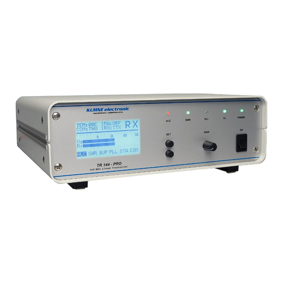
TR144-PRO 2 m Linear Transverter
Bedienungsanleitung / User Manual
TR144 PRO
2m Linear Transverter
shop.kuhne-electronic.de
Kuhne electronic GmbH
Scheibenacker 3
Telefon: +49 (0) 9293 / 800640
95180 Berg – Germany
E-Mail: info@kuhne-electronic.de
Solutions for the wireless world
V3.0 - 24.08.2017
Seite / page 1
Advertisement
Table of Contents

Related Manuals for Kuhne electronic TR144-PRO

Summary of Contents for Kuhne electronic TR144-PRO
- Page 1 TR144-PRO 2 m Linear Transverter Bedienungsanleitung / User Manual TR144 PRO 2m Linear Transverter V3.0 - 24.08.2017 shop.kuhne-electronic.de Seite / page 1 Kuhne electronic GmbH Scheibenacker 3 Telefon: +49 (0) 9293 / 800640 Solutions for the wireless world 95180 Berg – Germany...
- Page 2 Anforderungen angepasst und die Einzelkomponenten neu entwickelt. individual components redeveloped. Aim was to adapt TR144-PRO for most Ziel war es den TR144-PRO für die meisten auf dem Markt befindlichen HF- popular HF-Transceiver with just a few configuration steps and thereby be Tranceiver in wenigen Schritten konfigurierbar zu machen und dadurch den useful and universal.
- Page 3 TR144-PRO 2 m Linear Transverter Technische Daten / Specifications TR144-PRO Technische Daten / Specifications VHF Frequenzbereich VHF Frequency range 144...146 MHz ZF Frequenzbereich IF Frequency range 28...30 MHz ZF Frequenzbereich IF Frequency range 14...16 MHz(OPT05) ZF Eingangsleistung Hi IF Input power hi 1...50 mW, einstellbar / adjustable...
- Page 4 TR144-PRO 2 m Linear Transverter Messprotokoll / Test certificate TR144-PRO Technische Daten / Specifications Transverter: TR144-PRO SN: Opt: 05 Opt: S ZF Frequenz / IF frequency : 14...16 MHz 28...30 MHz Power LED: LED: LED: LED: LED: Display LED: Display Kontrast / Display contrast:...
- Page 5 TR144-PRO 2 m Linear Transverter Technische Daten 1 / Specifications 1 TR144-PRO Typische Werte /Typical Plots Typ. IP3 out bei 28 MHz ZF Typ. IP3 out bei 14 MHz ZF Typ. IP3out @28 MHz IF Typ. IP3out @14 MHz IF Typ.
- Page 6 TR144-PRO 2 m Linear Transverter Technische Daten 2 / Specifications 2 TR144-PRO Typische Werte /Typical Plots Typ. Oberwellenunterdrückung bei 25W CW Typ. IM3 bei 20W PEP Typ. Harmonic suppression at 25W CW Typ. IM3 @ 20W PEP Typ. LO Phasenrauschen bei 130 MHz (14 MHz ZF) Typ.
- Page 7 Eigenschaften immer nachvollziehbar. Sollte ihr TR144-PRO jedoch In case of a technical defect of your TR144-PRO you can contact us at any einmal eine Unregelmäßigkeit oder einen Defekt aufweisen, können Sie time. To provide best-possible support our service team has to know the sich jederzeit an uns wenden.
- Page 8 TR144-PRO 2 m Linear Transverter Bedienung 2 / Instructions 2 Bedienelemente /Control elements POWER GAIN TR 144 - PRO 1 4 4 M H z L i n e a r T r a n s v e r t e r...
- Page 9 TR144-PRO 2 m Linear Transverter Bedienung 3 / Instructions 3 Bedienelemente / Control elements ANT 1 IF A IF B ANT 2 IF C Serial Interface DC / Control IF-B IF-B ZF Anschluss B IF Connector B IF-A IF-A ZF Anschluss A IF Connector A Eingang für 10 MHz Referenzsignal...
- Page 10 TR144-PRO 2 m Linear Transverter Bedienung 4 / Instructions 4 Sicherung / Fuse Sollte es zum Auslösen der Sicherung oder anderer Störungen In case of a triggered fuse it can be replaced by opening the device kommen, kann nach Öffnen des Gerätedeckels die interne Sicherung cover.
- Page 11 Einschalten / Power On Einschalten: Switch On: Mit dem (ON) Schalter auf der Frontplatte wird der TR144-PRO Activate the transverter by pressing the (ON-Switch) on the front panel. eingeschaltet. Zunächst werden Testroutinen gestartet um die Immediately a initiation routine starts to check the state of the internal Peripherie zu aktivieren, die abgefragten Adressen oder Module blocks and address of built-in sensors.
- Page 12 Menu Mode: Der Transverter TR144-PRO kann über ein Konfigurationsmenü ohne The TR144-PRO comes with an easy-to-use Menu system which allows großen Aufwand und in nur wenigen Schritten an die gängigsten HF- the adaption of all common HF-Transceiver with a few steps only. The Transceiver angepasst werden.
- Page 13 TR144-PRO 2 m Linear Transverter Bedienung 7 / Instructions 7 Konfigurationsmenü / Configuration menu Einstellung Sequenzerzeiten: Adjusting Sequencer Time: Die eingebaute Ablaufsteuerung ist mit zwei aufeinanderfolgenden, vom The built-in sequencer comes with two consecutive freely usable Benutzer frei verwendbaren Ausgängen ausgestattet. Die zeitliche Abfolge outputs.
- Page 14 TR144-PRO 2 m Linear Transverter Bedienung 8 / Instructions 8 Konfigurationsmenü / Configuration menu Einstellung TRV CONVERTER SET: Setting TV CONVERTER SET: Diese Einstellung definiert das Verhalten der ZF Anschlüsse. Es gibt zwei This feature determines the behavior of the IF ports. There are two Möglichkeiten:...
- Page 15 TR144-PRO 2 m Linear Transverter Bedienung 9 / Instructions 9 Konfigurationsmenü / Configuration menu Einstellung TRV TX AMP SET: Setting TRV TX AMP SET: Diese Einstellung aktiviert oder deaktiviert den Sende-ZF Verstärker. Dies This enables or disables the transmit IF amplifier. Through that the ermöglicht es, einen großen TX-ZF-Eingangsbereich zu überstreichen.
-
Page 16: Table Of Contents
Einstellung TRV ANTENNA SETTING: Setting TRV ANTENNA SETTING: Der TR144-PRO verfügt über zwei gleichwertige Antennenanschlüsse. Dies The TR144-PRO comes with two equivalent antenna connectors. This ermöglicht eine frei konfigurierbare Konstellation welcher Anschluss für offers a freely configurable constellation which connector is used for Empfang und Senden genutzt werden soll. -
Page 17: If Bref
TR144-PRO 2 m Linear Transverter Betrieb 1 / Operation 1 Rückseitige Anschlüsse / Rear Panel Connections ANT 1 IF A IF B ANT 2 IF C Serial Interface DC / Control Anschlüsse IF A / IF B und IF C: Jacks IF A / IF B and IF C: Die Anschlüsse IF A...IF C bilden die Gruppe Zwischenfrequenzanschlüsse... -
Page 18: If Bref
TR144-PRO 2 m Linear Transverter Betrieb 2 / Operation 2 Rückseitige Anschlüsse / Rear Panel Connections ANT 1 IF A IF B ANT 2 IF C Serial Interface DC / Control Anschlüsse LO und REF: LO and REF Jack: Die Buchsen sind in BNC-Norm ausgeführt und verfügen über eine The connectors are standard BNC with an impedance of 50Ω. -
Page 19: If Bref
TR144-PRO 2 m Linear Transverter Betrieb 3 / Operation 3 Anschlüsse / Wiring ANT 1 IF A IF B ANT 2 IF C Serial Interface DC / Control Anschlüsse ANT 1 und ANT 2: Jack ANT 1 and ANT 2: Die Antennenanschlüsse sind N-Norm mit einer Impedanz von 50Ω... - Page 20 DC / Control Serial Interface : Serial Interface : Das serielle Interface ermöglicht eine Steuerung des TR144-PRO und eine A possibility to control the TR144-PRO and receive information about Ausgabe der internen Funktionen. Aktiver Datenaustausch wird mit einem internal functions is given by the serial interface. Active data exchange will Symbol im Display angezeigt.
- Page 21 4,5 and 7,8,9. Anschlüssen 4/5 und 7/8/9 zum Einsatz kommen. The applied voltage is monitored continuously. The TR144-PRO is Der TR144-PRO ist mit einer Feinsicherung gegen Überstrom fuse-protect from over-current. How to exchange a blown fuse is gesichert.
- Page 22 Pin 6 acts as the PTT input (push to talk). Connecting it to ground unbedingt beschaltet werden. Die mittels Pullup-Widerstand (GND) will set the TR144-PRO to transmitting mode. A connection of angelegte Spannung darf den spezifizierten Bereich nicht this pin is absolutely necessary. The voltage applied though a pull-up überschreiten.
- Page 23 TR144-PRO 2 m Linear Transverter Betrieb 7 / Operation 7 DC Versorgungskabel / DC Power and control cord Anschlussbelegung der SUB-D Steckverbindung Wiring of SUB-D plug-in connector shop.kuhne-electronic.de Seite / page 23 Kuhne electronic GmbH Scheibenacker 3 Telefon: +49 (0) 9293 / 800640 Solutions for the wireless world 95180 Berg –...
- Page 24 Under normal condition the SWR-LED shows green after Startsequenz. Wird im Sendebetrieb ein VSWR schlechter 1:2 startup. If the VSWR becomes worse than 1:2 the TR144-PRO detektiert, wechselt der TR144-PRO sofort in changes into receiving mode immediately and the SWR-LED Empfangsmodus und die SWR-LED schaltet auf Rot.
- Page 25 Wird der PTT-Anschluss (Pin 6 des DC/Control-Eingangs) startup. Grounding the PTT-Input (Pin 6 on DC / Control gegen Masse gezogen schaltet der TR144-PRO auf Sende- jack) the TR144-PRO switches into transmitting mode. Betrieb um. Ist dieser Vorgang abgeschlossen, wechselt die Is the switching-sequence completed the RX/TX-LED shows RX/TX-LED auf Rot.
- Page 26 Summary of different IF configurations of the TR144-PRO: Diese Liste bietet eine Übersicht möglicher Konfigurationen des This list is just a summary of the possible configurations of the TR144-PRO TR144-PRO in Abhängigkeit des verwendeten HF-Transceivers. Die hier depending on the used RF-Transceiver. The shown configurations are not...
- Page 27 TR144-PRO 2 m Linear Transverter Tranceiver 2 / Tranceiver 2 Beispiel / Example FT 757GX Beim Verbinden des FT-757GX mit dem Transverter sind die Consider the modification instructions given in the transceivers manual Umbauhinweise im Handbuch des KW-Transceivers zu beachten. Dies gilt when wiring up the FT-757GX.
- Page 28 TR144-PRO 2 m Linear Transverter Tranceiver 3 / Tranceiver 3 Beispiel / Example TS850 Beim Verbinden des TS-850 mit dem Transverter sind die Umbauhinweise Consider the modification instructions given in the transceivers manual im Handbuch des KW-Transceivers zu beachten. Dies gilt besonders für die when wiring up the TS-850.
- Page 29 TR144-PRO 2 m Linear Transverter Tranceiver 4 / Tranceiver 4 Beispiel / Example IC 756Pro Bei der Verbindung des IC756PRO II/III mit einem externen Transverter Follow the instructions of the IC756PRO II/III handbook for how to sind die Hinweise im Handbuch des Kurzwellentransceivers zu beachten.
- Page 30 The IC 7700 comes with a 10 MHz reference signal output. It can be used to Dieses 10 MHz Referenzsignal kann zur Verbesserung der stabilize the LO of the TR144-PRO. Since the level of that reference signal is Frequenzstabilität des Lokaloszillators im TR144RO verwendet werden. Da...
- Page 31 TR144-PRO 2 m Linear Transverter Tranceiver 6 / Tranceiver 6 Beispiel / Example ANAN 100 Beim Verbinden des ANAN 100 mit einem Transverter sind die Follow the instructions of the ANAN 100 handbook for how to Betriebshinweise im Handbuch des ANAN 100 zu beachten.
- Page 32 Funktionen, die eine Aktion des TR144-PRO bewirken und mit einem „w“ wie „write“ angeführt werden und Functions leading to an action of the TR144-PRO are led in by a “w” like Ausgaben, die lediglich eine Ausgabe von Daten bewirken und mit “write“...
- Page 33 The current consumption should be about 200 mA. 200 mA. Erfolgt eine Abschaltung des TR144-Pro im Sleep Mode If the TR144-PRO is powered off during sleep mode it will resume wird nach dem erneutem Einschalten mit normaler Funktion normal operation after power-up. Activated sleep-function will not gestartet.
- Page 34 TR144-PRO 2 m Linear Transverter Software 3 / Software 3 Fernsteuerung / Remotecontrol >w< Steuert die Konfiguration der ANTx Anschlüsse >w< This feature determines the behavior of the ANTx ports >TRV ANTENNA SET<. >TRV ANTENNA SET<. Die Umschaltung ist nur im Empfangsmode möglich.
- Page 35 Procedure: Während des Firmwareupdates ist die Spannungsversorgung des TR144- During a firmware update the TR144-PRO and the PC / notebook require a PRO und dem verwendetem PC / Laptop zu gewährleisten. Es ist möglich reliable power supply. The transverter can draw a maximum of 2.5A while dass der TR144-PRO im Prozess des Firmwareupdates kurzfristig bis zu updating (quiescent current).
- Page 36 TR144-PRO 2 m Linear Transverter Fehlersuche / Troubleshooting Checkliste / Checklist Gerät startet nicht, alle LEDs und das Display bleiben dunkel Device doesn’t start, all the LEDs and the display remain dark? - Kontrolle der Anschlüsse, korrekte Verschaltung? - Checkup of all connections, wiring correct? - Stimmen Betriebsspannung und Polarität?
- Page 37 TR144-PRO 2 m Linear Transverter Blockschaltbild/ Block diagram shop.kuhne-electronic.de Seite / page 37 Kuhne electronic GmbH Scheibenacker 3 Telefon: +49 (0) 9293 / 800640 Solutions for the wireless world 95180 Berg – Germany E-Mail: info@kuhne-electronic.de...
Need help?
Do you have a question about the TR144-PRO and is the answer not in the manual?
Questions and answers