
Related Manuals for Metek Powervar Security II Series


Summary of Contents for Metek Powervar Security II Series
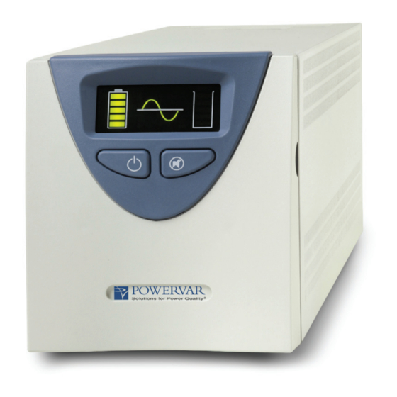
- Page 1 Security II Series Uninterruptible Power Manager For use with 420VA, 600VA, 800VA, 1100VA ,1440VA, 2200VA, and 3000VA RoHS Compliant Uninterruptible Power Manager...
-
Page 2: Table Of Contents
TABLE OF CONTENTS 1.0 - Introduction ..............2.0 - Safety Instructions ............3.0 - Installation ..............4.0 - Operation ..............5.0 - Maintenance ............... 6.0 - Specifications ............. 7.0 - Troubleshooting ............8.0 - Warranty ..............9.0 - Francais ..............1.0 - Introduction. - Page 3 IMPORTANT NOTICE ON BATTERY WARRANTY The warranty policy stated in Section 8 is not valid for applications in which the Uninterruptible Power Manager (UPM) is regularly and intentionally disconnected from AC mains power. AMETEK Powervar’s battery warranty applies only to products that are properly installed and consistently connected to AC mains power, except during utility outages.
- Page 4 Danger- The danger symbol is used to indicate imminently hazardous situations, locations, and conditions which, if not avoided, WILL result in death, serious injury, and/or severe property damage. DANGER Caution- The caution symbol is used to indicate potentially hazardous situations and conditions which, if not avoided, may result in injury.
-
Page 5: Introduction
1.0 INTRODUCTION Thank you for your purchase of the AMETEK Powervar Security II Series UPM (hereafter referred to as “UPM”). AMETEK Powervar manufactures two versions of the UPM – a standard version, and a medical version listed to UL60601-1 and cUL C22.2 No. 60601.1. In addition, all models are compatible with International electrical distribution systems. -
Page 6: Safety Instructions
2.0 SAFETY INSTRUCTIONS IMPORTANT - SAVE THESE INSTRUCTIONS THIS MANUAL CONTAINS IMPORTANT SAFETY INSTRUCTIONS. KEEP THIS MANUAL HANDY FOR REFERENCE. CAUTION A battery can present a risk of electrical shock. Short-circuit currents can be extremely high and can create severe burns as well as the risk of fire or explosion from vented gases. - Page 7 Statement of Intended use The medical UPMs are intended to protect medical, non-medical computer equipment and medical devices that need battery backup, surge protection, voltage regulation and line noise filtering in and around patient care areas. Safe and continuous operation of the UPM depends partially on the care taken by users.
- Page 8 • The total leakage current of the UPM and consumer connected equipment should not exceed 3.5 mA for non-medical units. • Not for use in a computer room as defined in the Standard for the Protection of Electronic Computer/Data Processing Equipment, ANSI/NFPA 75.
- Page 9 This equipment generates, uses and can radiate radio frequency energy and if not installed and used in accordance with the instructions, may cause harmful interference to radio communications. However, there is no guarantee that interference will not occur in a particular installation. If this equipment does cause harmful interference to radio and/or television reception, which can be determined by turning the UPM equipment on and off, the user is encouraged to try to correct the interference by one...
-
Page 10: Installation
3.0 INSTALLATION Inspecting the UPM If any equipment has been damaged during shipment, keep the shipping cartons and packing materials for the carrier or place of purchase and file a claim for shipping damage: 1. File with the carrier within 15 days of receipt of the equipment; 2. - Page 11 Quick Start Guide This unit is shipped with the internal batteries disconnected. Before starting the UPM, please follow these battery connection instructions. Remove UPM from the box Plug UPM into the wall Remove UPM front cover and Put front cover back on and connect battery connector remove the yellow warning label IMPORTANT...
- Page 12 Unpacking the UPM CAUTION • Unpacking the unit in a low-temperature environment may cause condensation to occur in and on the unit. Do not install the unit until the inside and outside of the unit are absolutely dry {hazard of electric shock}.
- Page 13 Applying Power to the UPM Connect the power cord to a verified grounded 3 wire receptacle. Verify that the Site Wiring Fault “SF” is off (120 VAC models only). Once properly connected and initially checked, turn on the UPM by pressing and holding the front panel On/Off switch for 3 seconds.
- Page 14 Operational Tests Observe the front panel of the UPM. The following table shows system status behavior. UPM Front Panel UPM LED DISPLAY UNIT STATUS UPM output on Battery charge status in 20% increments UPM load status in 20% increments UPM in battery operation due to improper incoming AC voltage UPM overloaded Battery fault or battery disconnected Unit in buck operation due to high incoming AC voltage...
- Page 15 UPM Load and Battery Indicators UPM display showing normal operation (Fully charged batteries with 60% load shown) UPM display showing in battery backup operation (Batteries 80% charged with 60% load shown) UPM display showing an overload condition (Batteries 100% charged and greater than 100% load shown) UPM display showing over-temperature condition (Batteries 80% charged with 80% load shown) UPM display showing a bad battery condition...
- Page 16 Silence button or unplugging the UPM. When this final test is completed, the UPM will be ready to use. Reference the below UPM fault code chart to identify the status of the UPM. UPM Status Code Definition Inverter fault Back-Feed fault Unit is off due to a high line Unit is off due to a low line Unit is off due to a low battery...
-
Page 17: Operation
4.0 OPERATION On/Off Button The On/Off button is a dual function control: • When the UPM is off and AC power is present to the UPM input, pressing the On/Off button for more than 2 seconds will turn the UPM output on. •... - Page 18 Site Wiring Fault Indicator – (120 VAC models only) The SF symbol will be displayed on the front panel of the UPM if it is connected to an improperly wired AC receptacle. This is to indicate a missing safety ground wire or a reversal in phase and neutral wiring. If the “SF”...
- Page 19 Windows and Linux, http://connectivity.powervar.com/products/ mopups-pro/ SCENARIO B: Shutdown more than one computer sharing the UPM output power, or in applications where any computers are more than 6 feet from the UPM. • Purchase the optional ManageUPS Net adapter (SNMP/WEB card, PN: AM-P1-R2), install it in the Extended Communications Slot of the UPM and connect it to the TCP/IP LAN that the computers are connected to.
- Page 20 • If your system is compatible with “simulated relay contact” or designed for active high/iow 12VDC signals, use the DB9 Port on UPM back panel. This port provides access to basic-signal interfaces for use with some industrial control systems or with legacy and open source UPM monitoring software to trigger automated computer shutdown on low battery conditions.
- Page 21 SCENARIO B: Monitor UPM Health and Power Quality via existing SNMP monitoring system. • Use the same option described in Scenario A. Configure the RFC1628 compliant SNMP agent via the WEB interface of the ManageUPS Net Adaper. SCENARIO C: Monitor UPM Health and Site Power Quality via existing BMS (Building Monitoring System) via MODBUS RTU or MODBUS TCP.
- Page 22 ManageUPS Net Adapter for load shedding or sequenced startup. • Remote power off/on control via WEB browser to reboot or control specific loads on the UPM. Screen capture below shows the main menu for accessing controls for the Integrated Switched PDU. AUTOMATED LOAD SHEDDING TO SAVE BATTERY POWER FOR OTHER LOADS Screen capture below shows the main menu in the WEB interface...
- Page 23 PROGRAM DIFFERENT RESTART DELAYS TO STAGE AUTOMATED SYSTEM START UP ON POWER FAIL RECOVERY Screen capture below shows how automated shutdown and restart delays can be configured for each socket group through the WEB interface of the ManageUPS Net Adapter. NOTE: Battery-Off Delay control would be configured via the Network Shutdown Controller function if the load on a socket is a computer...
- Page 24 NOTE: Pin 5 should only be connected to ground. A01-00055 Rev M...
- Page 25 NOTE: You may, of course, connect your computer to the UPM without using software. When power is lost, the UPM will beep and you will have to manually shut down the computer and UPM. Start Manager When AC power is not available, such as in a new installation where wiring may be incomplete, you can still start the UPM to test its operation and the operation of your system using Start Manager.
-
Page 26: Maintenance
5.0 MAINTENANCE STORAGE A charged battery, disconnected from a UPM or load, can maintain ideal voltage for approximately six months before recharge is necessary. A discharged battery needs to be recharged within 72 hours of the discharge to avoid permanent battery damage. Storing a UPM with the battery connected can cause permanent battery damage and therefore, the battery must always be disconnected when storing the UPS. - Page 27 • AC is removed, the output is turned off, and the battery is connected. • Operating on battery back-up (no AC present) and output is turned off or the battery is depleted. Deeply Discharged Battery Alarm – when detected will flash the pattern below and sound the audible alarm, indicating to remove AC Power, and call AMETEK Powervar service for a battery replacement at 1-800-369-7179.
- Page 28 at least six hours to charge without a power interruption. Inadequate (much shorter than usual) backup time, premature low battery alarm sounds, and persistent Low/Replace Battery LED illumination are all good signs that the batteries inside your UPM requires replacement. The batteries inside your UPM are designed to be replaced by an authorized service personnel only.
- Page 29 User Replaceable Battery (Non-medical units only) Eventually every UPM requires a new battery. AMETEK Powervar expects the battery in your UPM to last a minimum of two years – perhaps longer if power outages are short and infrequent. The UPM makes battery replacement by the user fast and easy.
- Page 30 CAUTION Risk of Energy Hazard, 12V, maximum 8.5 Ampere-hour batteries. Before replacing batteries, remove conductive jewelry such as chains, wrist watches, and rings. High energy through conductive materials could cause severe burns. CAUTION Do not dispose of batteries in a fire. The batteries may explode. CAUTION Do not open or mutilate batteries.
- Page 31 Battery Replacement (Non-medical units only) 1. Carefully pull the front panel away from the unit. The panel should pop loose. (Refer to figure on page 13) 2. Disconnect the red and black connector from each other. 3. Loosen the (2) thumb screws that attach the battery door to the unit.
-
Page 32: Specifications
6.0 SPECIFICATIONS North American Models ABCE422-11 and ABCE422-11MED ABCE422-11 ABCE422-11MED 50042-02R 50042-22R Type Standard Medical Grade Power Rating (VA/Watts) 420 / 378 420 / 378 Inverter Waveform Low Distortion Sine Wave Low Distortion Sine Wave Transfer Time 4 ms. Typical 4 ms. - Page 33 North American Models ABCE422-11 and ABCE422-11MED Front Panel Controls Safety Agency and EMC Compliance: All Units are Listed by UL and Marked With the UL/cUL Marking • Power On/Off • Test • Load Level LED Gauge Standard UPM: Products Listed to: •...
- Page 34 North American Models ABCE602-11 and ABCE602-11MED ABCE602-11 ABCE602-11MED 50060-03R 50060-23R Type Standard Medical Grade Power Rating (VA/Watts) 600 / 540 600 / 540 Inverter Waveform Low Distortion Sine Wave Low Distortion Sine Wave Transfer Time 4 ms. Typical 4 ms. Typical Frequency 60 Hz.
- Page 35 North American Models ABCE602-11 and ABCE602-11MED Front Panel Controls Safety Agency and EMC Compliance: All Units are Listed by UL and Marked with the UL/cUL Marking • Power On/Off • Test • Load Level LED Gauge Standard UPM: Products Listed to: •...
- Page 36 North American Models ABCE802-11 and ABCE802-11MED ABCE802-11 ABCE802-11MED 50080-03R 50080-23R Type Standard Medical Grade Power Rating (VA/Watts) 800 / 720 800 / 720 Inverter Waveform Low Distortion Sine Wave Low Distortion Sine Wave Transfer Time 4 ms. Typical 4 ms. Typical Frequency 60 Hz.
- Page 37 North American Models ABCE802-11 and ABCE802-11MED Front Panel Controls Safety Agency and EMC Compliance: All Units are Listed by UL and Marked with the UL/cUL Marking • Power On/Off • Test • Load Level LED Gauge Standard UPM: Products Listed to: •...
- Page 38 North American Models ABCE1102-11 and ABCE1102-11MED ABCE1102-11 ABCE1102-11MED 50110-03R 50110-23R Type Standard Medical Grade Power Rating (VA/Watts) 1100 / 990 1100 / 990 Inverter Waveform Low Distortion Sine Wave Low Distortion Sine Wave Transfer Time 4 ms. Typical 4 ms. Typical Frequency 60 Hz.
- Page 39 North American Models ABCE1102-11 and ABCE1102-11MED Front Panel Controls Safety Agency and EMC Compliance: All Units are Listed by UL and Marked with the UL/cUL Marking • Power On/Off • Test • Load Level LED Gauge Standard UPM: Products Listed to: •...
- Page 40 North American Models ABCE1442-11 and ABCE1442-11MED ABCE1442-11 ABCE1442-11MED 50144-03R 50144-23R Type Standard Medical Grade Power Rating (VA/Watts) 1440 / 1296 1440 / 1296 Inverter Waveform Low Distortion Sine Wave Low Distortion Sine Wave Transfer Time 4 ms. Typical 4 ms. Typical Frequency 60 Hz.
- Page 41 North American Models ABCE1442-11 and ABCE1442-11MED Front Panel Controls Safety Agency and EMC Compliance: All Units are Listed by UL and Marked with the UL/cUL Marking • Power On/Off • Test • Load Level LED Gauge Standard UPM: Products Listed to: •...
- Page 42 North American Models ABCE2202-11 and ABCE3002-11 ABCE2202-11 ABCE3002-11 50220-05R 50300-05R Type Standard Medical Grade Power Rating (VA/Watts) 1800 / 1620 1800 / 1620 Inverter Waveform Low Distortion Sine Wave Low Distortion Sine Wave Transfer Time 4 ms. Typical 4 ms. Typical Frequency 50 / 60 Hz.
- Page 43 North American Models ABCE2202-11 and ABCE3002-11 Front Panel Controls Safety Agency and EMC Compliance: • Power On/Off All Units are Listed by UL and Marked with the UL/cUL Marking • Test • Load Level LED Gauge Standard UPM: • Battery Charge LED Gauge Products Listed to: •...
- Page 44 North American Models ABCE2202-11 and ABCE3002-11 ABCE2202-11 ABCE3002-11 50220-03R 50300-03R Type Standard Medical Grade Power Rating (VA/Watts) 2200 / 1980 2760 / 2484 Inverter Waveform Low Distortion Sine Wave Low Distortion Sine Wave Transfer Time 4 ms. Typical 4 ms. Typical Frequency 50 / 60 Hz.
- Page 45 North American Models ABCE2202-11 and ABCE3002-11 Front Panel Controls Safety Agency and EMC Compliance: • Power On/Off All Units are Listed by UL and Marked with the UL/cUL Marking • Test Standard UPM: • Load Level LED Gauge Products Listed to: •...
- Page 46 International Models ABCE422-22 and ABCE422-22MED ABCE422-22 ABCE422-22MED 51042-02R 51042-22R Type Standard Medical Grade Power Rating (VA/Watts) 420 / 378 420 / 378 Inverter Waveform Low Distortion Sine Wave Low Distortion Sine Wave Transfer Time 4 ms. Typical 4 ms. Typical Frequency 50 / 60 Hz.
- Page 47 International Models ABCE422-22 and ABCE422-22MED Front Panel Controls Safety Agency and EMC Compliance: • Power On/Off All Units are Listed by UL and Marked with the UL/cUL Marking • Test • Load Level LED Gauge Standard UPM: • Battery Charge LED Gauge Products Listed to: •...
- Page 48 International Models ABCE602-22 and ABCE602-22MED ABCE602-22 ABCE602-22MED 51060-03R 51060-23R Type Standard Medical Grade Power Rating (VA/Watts) 600 / 540 600 / 540 Inverter Waveform Low Distortion Sine Wave Low Distortion Sine Wave Transfer Time 4 ms. Typical 4 ms. Typical Frequency 50 / 60 Hz.
- Page 49 International Models ABCE602-22 and ABCE602-22MED Front Panel Controls Safety Agency and EMC Compliance: • Power On/Off All Units are Listed by UL and Marked with the UL/cUL Marking • Test • Load Level LED Gauge Standard UPM: • Battery Charge LED Gauge Products Listed to: •...
- Page 50 International Models ABCE802-22 and ABCE802-22MED ABCE802-22 ABCE802-22MED 51080-03R 51080-23R Type Standard Medical Grade Power Rating (VA/Watts) 800 / 720 800 / 720 Inverter Waveform Low Distortion Sine Wave Low Distortion Sine Wave Transfer Time 4 ms. Typical 4 ms. Typical Frequency 50 / 60 Hz.
- Page 51 International Models ABCE802-22 and ABCE802-22MED Front Panel Controls Safety Agency and EMC Compliance: • Power On/Off All Units are Listed by UL and Marked with the UL/cUL Marking • Test • Load Level LED Gauge Standard UPM: • Battery Charge LED Gauge Products Listed to: •...
- Page 52 International Models ABCE1102-22 and ABCE1102-22MED ABCE1102-22 ABCE1102-22MED 51110-03R 51110-23R Type Standard Medical Grade Power Rating (VA/Watts) 1100 / 990 1100 / 990 Inverter Waveform Low Distortion Sine Wave Low Distortion Sine Wave Transfer Time 4 ms. Typical 4 ms. Typical Frequency 50 / 60 Hz.
- Page 53 International Models ABCE1102-22 and ABCE1102-22MED Front Panel Controls Safety Agency and EMC Compliance: • Power On/Off All Units are Listed by UL and Marked with the UL/cUL Marking • Test • Load Level LED Gauge Standard UPM: • Battery Charge LED Gauge Products Listed to: •...
- Page 54 International Models ABCE1442-22 and ABCE1442-22MED ABCE1442-22 ABCE1442-22MED 51144-03R 51144-23R Type Standard Medical Grade Power Rating (VA/Watts) 1440 / 1296 1440 / 1296 Inverter Waveform Low Distortion Sine Wave Low Distortion Sine Wave Transfer Time 4 ms. Typical 4 ms. Typical Frequency 50 / 60 Hz.
- Page 55 International Models ABCE1442-22 and ABCE1442-22MED Front Panel Controls Safety Agency and EMC Compliance: • Power On/Off All Units are Listed by UL and Marked with the UL/cUL Marking • Test Standard UPM: • Load Level LED Gauge Products Listed to: •...
- Page 56 International Models ABCE2202-22 and ABCE2202-22MED ABCE2202-22 ABCE2202-22MED 51220-03R 51220-23R Type Standard Medical Grade Power Rating (VA/Watts) 2200 / 1980 2200 / 1980 Inverter Waveform Low Distortion Sine Wave Low Distortion Sine Wave Transfer Time 4 ms. Typical 4 ms. Typical Frequency 50 / 60 Hz.
- Page 57 International Models ABCE2202-22 and ABCE2202-22MED Front Panel Controls Safety Agency and EMC Compliance: • Power On/Off All Units are Listed by UL and Marked with the UL/cUL Marking • Test Standard UPM: • Load Level LED Gauge Products Listed to: •...
- Page 58 International Models ABCE3002-22 and ABCE3002-22MED ABCE3002-22 ABCE3002-22MED 51300-03R 51300-23R Type Standard Medical Grade Power Rating (VA/Watts) 3000 / 2700 3000 / 2700 Inverter Waveform Low Distortion Sine Wave Low Distortion Sine Wave Transfer Time 4 ms. Typical 4 ms. Typical Frequency 50 / 60 Hz.
- Page 59 International Models ABCE3002-22 and ABCE3002-22MED Front Panel Controls Safety Agency and EMC Compliance: • Power On/Off All Units are Listed by UL and Marked with the UL/cUL Marking • Test Standard UPM: • Load Level LED Gauge Products Listed to: •...
-
Page 60: Troubleshooting
7.0 TROUBLESHOOTING The troubleshooting information provided in this section should help you discover the cause of most commonly encountered difficulties. Before following the troubleshooting steps provided, be certain that you have verified the following items: • The UPM should be plugged into a properly working outlet. •... - Page 61 Output Fuse Rating Chart Work to be done only by qualified service personnel. It is critical that the same type and rating of fuses are used: Replace with same type and rating of fuse fuse must be rated to IEC 60127-2 Model Fuse rating (slo-blo) ABCE422-11MED...
-
Page 62: Warranty
8.0 WARRANTY The AMETEK Powervar Security II Series UPM is warranted to be free from defects in material and workmanship for sixty (60) months from date of shipment from AMETEK Powervar, on the chassis & electronic components and twenty four (24) months from date of shipment from AMETEK Powervar on the batteries. -
Page 63: Francais
9.0 FRANCAIS AVIS IMPORTANT SUR LA GARANTIE DE LA BATTERIE La politique de garantie énoncée à la section 8 n’est pas valide pour les applications où le gestionnaire d’alimentation sans interruption (UPM) est débranché régulièrement et intentionnellement du secteur. La garantie offerte par AMETEK Powervar pour les batteries ne s’applique qu’aux produits installés correctement et connectés constamment au secteur, sauf lors des pannes de courant. - Page 64 Danger - Le symbole danger est utilisé pour signaler les situations, emplacements et conditions qui, s’ils ne sont pas évités, CAUSERONT la mort, des blessures sérieuses et/ou des dommages matériels importants. DANGER Attention - Le symbole attention est utilisé pour signaler les situations et les conditions potentiellement dangereuses qui, si elles ne sont pas évitées, peuvent causer des blessures.
-
Page 65: Introduction
1.0 INTRODUCTION Nous vous remercions pour votre achat de l’AMETEK Powervar Security II Séries UPM (ci-après dénommé « UPM »). AMETEK Powervar fabrique deux versions de l’UPM – une version standard, une version médicale répertoriée UL60601-1 et C22.2 No. 60601.1. En outre, tous les modèles sont compatibles avec les systèmes internationaux de distribution électrique. -
Page 66: Consigne De Sécurité
2.1 CONSIGNES DE SÉCURITÉ IMPORTANT - CONSERVEZ CES INSTRUCTIONS CE MANUEL CONTIENT DES CONSIGNES DE SÉCURITÉ IMPORTANTES. CONSERVEZ CE MANUEL À PORTÉE DE MAIN COMME RÉFÉRENCE. ATTENTION Une batterie peut présenter un risque de décharge électrique. Les courants de court-circuit peuvent être extrêmement élevés et peuvent provoquer des brûlures sérieuses ainsi que des incendies ou l’explosion de gaz présents dans l’atmosphère. - Page 67 surintensités d’un maximum de 20 ampères, en conformité avec le Code national de l’électricité, ANSI/NFPA 70. • L’UPM est équipé de sa propre source interne d’énergie (batterie). Les prises de sortie de l’UPM peuvent être sous tension, même lorsque celui- ci n’est pas branché sur une alimentation CA. Déclaration d’utilisation prévue Les UPM médicaux sont destinés à...
- Page 68 • Ne pas laisser de liquide ou un objet étranger pénétrer dans l’UPM. • Ne pas bloquer les aérations sur le côté de l’UPM. Garder un minimum de 8 cm sur tous les côtés. • Ne pas brancher des appareils comme des sèche-cheveux, des ventilateurs, des radiateurs, etc.
- Page 69 Réglementation FCC Attention Cet UPM a été testé et il a été déterminé qu’il est conforme aux limites pour les appareils digitaux de classe A (conformité à la classe B en option), selon la partie 15 des réglementations de la FCC (Commission fédérale des communications des États-Unis).
-
Page 70: Installation
3.1 INSTALLATION Inspection de l’UPM Si une partie quelconque de l’équipement a été endommagée pendant l’expédition, conservez les boîtes et les matériaux d’emballage pour le transporteur ou le lieu d’achat et soumettez une réclamation pour dommages lors de l’expédition: 1. Déposez-la auprès du transporteur dans les 15 jours suivants la réception de l’équipement;... - Page 71 Guide de démmarage rapide SECURITY II Guide de démmarge rapide L’UPM est livré avec les batteries internes déconnectées. Avant de le mettre en marche, SVP suivre la procédure suivante. Retirez ie UPS de la boîte Retirez le UPS de laboîte Retirez le couvercle en façade et Remettre le couvercle et retirez branchez le connecteur...
- Page 72 Déballage de l’UPM ATTENTION • Déballer l’appareil dans un environnement froid peut entraîner la formation de condensation sur et dans l’appareil. N’installez pas l’appareil avant que l’intérieur et l’extérieur soient absolument secs {danger de décharge électrique}. • L’appareil est lourd. Prenez des précautions lors du déballage et du déplacement de l’appareil.
- Page 73 L’emplacement doit permettre une ventilation suffisante autour de l’UPM. Prévoyez un dégagement de minimum 7,6 cm sur tous les côtés pour une bonne ventilation. Mise sous tension de l’UPM Branchez le cordon d’alimentation à une prise vérifiée à 3 broches mise à...
- Page 74 Tests de fonctionnement Observez le panneau avant de l’UPM. Le tableau suivant montre les états du système. Panneau avant UPM LED DISPLAY UNIT STATUS Alimentation disponible á la sortie du UPM Niveau de charge des batteries par segments de 20% Niveau des charges protègées par segments de 20% Alimentation sur batteries Surcharge du UPS...
- Page 75 Affichage UPM indiquant une surchauffe (Batteries chargées à 80% avec une charge de 80% indiquée) Affichage UPM indiquant une batterie en mauvais état (In- specter ou remplacer la batterie chargée à 60%) REMARQUE: Selon l’état de charge de la batterie, il est possible que les DEL de niveau de charge de la batterie clignotent (c’est normal).
- Page 76 Code d’état UPM Définition Défaillance de l’inverseur Défaillance de réalimentation Appareil éteint en raison d’une tension élevée Appareil éteint en raison d’une tension basse Appareil éteint en raison d’une batterie faible Défaillance du ventilateur Défaut de câblage du site REMARQUE: •...
-
Page 77: Fonctionnement
4.1 FONCTIONNEMENT Bouton On/Off (marche/arrêt) Le bouton On/Off a deux fonctions: • Lorsque l’UPM est éteint et que la tension CA est présente à l’entrée de l’UPM, appuyer sur ce bouton pendant plus de 2 secondes allumera l’UPM. • Si la batterie est connectée, appuyer sur le bouton On/Off pendant au moins 2 secondes entraînera un «... - Page 78 Indicateur de défaut de câblage du site (modèles de 120 VCA uniquement) Le symbole SF s’affichera sur le panneau avant de l’UPM si celui-ci est connecté à une prise CA mal câblée. L’indicateur est prévu pour indiquer l’absence de mise à la terre de sécurité ou une inversion entre le neutre et la phase.
- Page 79 faible. Si vous voulez des fonctionnalités supplémentaires, y compris : la consignation des données et des événements, des fichiers de commande d’exécution automatique avant l’arrêt, l’accès à la configuration UPM et à l’agent de réseau intégré pour la surveillance centralisée via le logiciel AMETEK Powervar ManageUPS® CIO Server, le téléchargement et l’utilisation du logiciel AMETEK Powervar MopUPS®...
- Page 80 REMARQUE: La broche 5 doit être reliée uniquement à la terre. REMARQUE: Vous pouvez évidemment connecter votre ordinateur à l’UPM sans utiliser le logiciel. En cas de perte d’alimentation, l’UPM émettra un bip et vous devrez arrêter manuellement l’ordinateur et l’UPM. Gestionnaire de démarrage Lorsque l’alimentation CA n’est pas disponible, par exemple dans une nouvelle installation dans laquelle le câblage n’est pas terminé,...
-
Page 81: Entretien
5.1 ENTRETIEN Entreposage L’UPM peut être entreposé pendant des périodes prolongées dans un environnement qui ne le soumette pas à des conditions extrêmes de température ou d’humidité. En cas d’entreposage de longue durée la batterie doit être chargée tous les six mois. Si le lieu d’entreposage est caractérisé... - Page 82 de courant alternatif) et la sortie est désactivée ou la batterie est déchargée. Alerte de batterie profondément déchargée : lorsque cette condition est détectée, le symbole ci-dessous clignote et l’alarme sonore se déclenche, indiquant de couper l’alimentation CA et de contacter le service AMETEK Powervar au 1-800-369-7179 pour procéder au remplacement de la batterie.
- Page 83 d’alimentation. Une durée d’autonomie inadéquate (beaucoup plus courte que d’habitude), un signal prématuré d’alarme sonore de batterie basse et une illumination persistante de la DEL Batterie basse/ Remplacer sont des signes certains que les batteries dans votre UPM doivent être remplacées. Les batteries dans votre UPM sont conçues pour être remplacées par un personnel autorisé...
- Page 84 • Ne pas ouvrir ou endommager les batteries. Cela pourrait libérer l’électrolyte qui est toxique pour l’environnement et dangereux pour la peau et les yeux. • Les batteries de rechange peuvent être commandées auprès de AMETEK Powervar par téléphone ou par notre site web www. powervar.
- Page 85 de remplacement de batterie corrects. Voir les références des kits de remplacement ci-dessous. Indice VA Référence de kit de remplacement de batterie 50842-01 600/800 50880-01 1100/1440 50814-01 2200/3000 50822-01 ATTENTION Risque de danger électrique, batterie de 12 V, maximum 8,5 ampères- heures.
- Page 86 déconnecter les bornes de la batterie. • Vérifiez que la batterie n’est pas mise à la terre par inadvertance. • Si elle est mise à la terre, retirez la source de terre. Le contact avec une batterie mise à la terre peut entraîner une électrocution. REMARQUE: Si vous avez lu et compris les avertissements précédant cette section, vous pouvez procéder comme suit.
- Page 87 Remplacement de la batterie (appareils non médicaux uniquement) 3. Tirez avec précaution sur le panneau avant pour le séparer de l’appareil. Le panneau devrait sortir facilement (Consultez la figure à la page 73). 4. Séparez les connecteurs rouge et noir l’un de l’autre. 5.
- Page 88 Gefahr - Das Gefahrsymbol wird zur Anzeige unmittelbar gefährlicher Situationen, Orte und Bedingungen verwendet, die bei Nichtvermeidung zu tödlichen oder schweren Verletzungen und/oder schweren Sachbeschädigungen führen WERDEN. GEFAHR Vorsicht - Das Vorsichtsymbol wird zur Anzeige potenziell gefährlicher Situationen und Bedingungen verwendet, die bei Nichtvermeidung zu Verletzungen führen können.
-
Page 89: Deutsch
10.0 DEUTSCH WICHTIG HINWEIS ZUR BATTERIEGARANTIE Die in Kapitel 8 angegebene Garantiebestimmungen gelten nicht für Anwendungen, bei denen der UPM regelmäßig und absichtlich von der AC-Netzversorgung getrennt wird. AMETEK Powervars zweijährige Batteriegarantie gilt nur für Produkte, die korrekt installiert wurden und mit Ausnahme von Netzausfällen durchgehend an die AC-Netzversorgung angeschlossen sind. -
Page 90: Einleitung
1.0 EINLEITUNG Vielen Dank, dass Sie sich für einen Kauf eines UPMs der Serie AMETEK Powervar Security II ( im Weiteren als „UPM“ bezeichnet) entschieden haben. AMETEK Powervar stellt zwei Versionen von UPMs her – eine Standardversion sowie eine nach UL60601-1 und cUL C22.2 Nr. -
Page 91: Sicherheitshinweise
2.1 SICHERHEITSHINWEISE WICHTIG - BEWAHREN SIE DIESE ANLEITUNGEN AUF DIESES HANDBUCH ENTHÄLT WICHTIGE SICHERHEITSHINWEISE. BEWAHREN SIE DIESES HANDBUCH FÜR SPÄTERE NACHSCHLAGEZWECKE AUF. VORSICHT Batterien können das Risiko eines Stromschlags aufweisen. Kurzschlussströme können extrem hoch sein und schwere Verbrennungen sowie ein Brand- oder Explosionsrisiko entwichener Gase verursachen. Treffen Sie immer die angebrachten Sicherheitsvorkehrungen. - Page 92 Sicherungsbemessung von 20 Ampere gemäß dem National Electric Code ANSI/NFPA 70 angeschlossen werden. • Das UPM-Gerät ist mit einer internen Energiequelle (Batterie) ausgestattet. Die Ausgangsbuchsen des UPM-Geräts können Spannung führen, auch wenn das UPM-Gerät nicht an eine Wechselstromquelle angeschlossen ist. Erklärung zur bestimmungsgemäßen Verwendung Die medizinischen UPM-Geräte sind für den Schutz von medizinischen und nicht-medizinischen Computern sowie medizinischen...
- Page 93 Steckdose mit Strom versorgt werden, die mit dem zusammen mit dem UPM-Gerät bereitgestellten Netzstecker übereinstimmt. • Stellen Sie das UPM-Gerät nicht in der Nähe von Wasser oder in einer übermäßig feuchten Umgebung auf. • Es dürfen keine Flüssigkeiten oder Fremdgegenstände in das Innere des UPM-Geräts gelangen.
- Page 94 Augen oder die Umwelt sein können. Batterien können das Risiko eines Stromschlags oder eines hohen Kurzschlussstroms aufweisen. Die folgenden Vorsichtsmaßnahmen sollten bei der Arbeit mit Batterien eingehalten werden: • Legen Sie Uhren, Ringe oder anderen Schmuck bzw. Gegenstände aus Metall ab, die in Kontakt mit der Batterie geraten können.
-
Page 95: Anschluss
3.1 ANSCHLUSS Inspektion des UPM-Geräts Falls Ausrüstungen während des Versands beschädigt wurden, bewahren Sie die Versandkartons und Verpackungsmaterialien für den Spediteur oder den Kaufort auf und reklamieren den Versandschaden wie nachstehend angegeben: 1. Melden Sie den Schaden innerhalb von 15 Tagen nach Erhalt der Ausrüstungen dem Spediteur;... - Page 96 Kurzanleitung Security II Kurzanleitung A01-00055 Rev M...
- Page 97 Auspacken des UPM-Geräts VORSICHT • Bei Auspacken des Geräts in einer Umgebung mit niedrigen Temperaturen kann Kondensation in und auf dem Gerät entstehen. Installieren Sie das Gerät erst, wenn die Innen- und Außenseite desselben vollständig trocken ist {Stromschlaggefahr}. • Das Gerät ist schwer. Gehen Sie beim Auspacken und Bewegen des Geräts vorsichtig vor.
- Page 98 kondensierenden Luftbedingungen. Am Standort sollte einen angemessenen Luftstrom rund um das UPM- Gerät vorhanden sein. Sehen Sie an allen Seiten einen Abstand von mindestens 75 mm für eine korrekte Belüftung vor. Einschalten des UPM-Geräts Schließen Sie das Netzkabel an einer verifizierten, geerdeten dreipoligen Steckdose an.
- Page 99 Betriebstests Prüfen Sie die Frontblende des UPM-Geräts. Die nachstehende Tabelle zeigt das Systemstatusverhalten an. UPM- Frontblende UPM-LED-ANZEIGE GERÄTESTATUS UPM-Ausgang ein Batterieladezustand in 20%igen Schritten UPM-Ladezustand in 20%igen Schritten UPM im Batteriebetrieb aufgrund ungeeigneter eingehender AC- Spannung UPM überlastet Batteriefehler oder Batterie getrennt Gerät im Buck-Betrieb aufgrund hoher eingehender AC-Spannung Gerät im Boost-Betrieb aufgrund hoher eingehender AC- Spannung...
- Page 100 UPM-Display zeigt Batterie im Übertemperaturzustand an (Batterien zu 80% geladen mit 80%iger Lastanzeige) UPM-Display zeigt einen schlechten Batteriezustand an (zu 60% geladene Batterieeinheit prüfen oder austauschen) HINWEIS: Abhängig vom Ladezustand der Batterie können die Batterieladezustand-LEDs eventuell blinken (dies ist normal). Erste Inbetriebnahme Führen Sie bei dem ausgeschalteten, angeschlossenen UPM-Gerät eine Erstprüfung der Backup-Funktion durch, indem Sie die Taste „Testen/...
- Page 101 UPM-Statuscode Definition Wechselrichterfehler Rückspeisefehler Gerät ist aufgrund einer hohen Leitung aus Gerät ist aufgrund einer niedrigen Leitung aus Gerät ist aufgrund einer niedrigen Batterie aus Lüfterfehler Fehler Standortverkabelung HINWEIS: • Falls das UPM-Gerät kontinuierlich eingeschaltet ist, führt es alle sechs Tage einen automatischen Batterietest durch. •...
-
Page 102: Betrieb
4.1 BETRIEB Ein-/Aus-Taste Die Ein-/Aus-Taste ist eine Doppelfunktionssteuerung: • Wenn das UPM-Gerät ausgeschaltet und AC-Strom am UPM- Eingang vorhanden ist, wird der UPM-Ausgang durch Drücken der Ein-/Aus-Taste während mehr als 2 Sekunden eingeschaltet. • Falls die Batterie angeschlossen ist, wird das UPM-Gerät bei Drücken des Ein-/Aus-Schalters während 2 Sekunden oder mehr über die interne Batterie ohne Vorhandensein von eingehendem Wechselstrom „kaltgestartet“. - Page 103 Batterielademonitor Der Batterielademonitor ist ein 5-Segment-LED-Display, das die Ladekapazität der internen Batterie von Null bis 100% anzeigt. Jede LED zeigt ca. 20% der vollen Ladung an. Anzeige Fehler Standortverkabelung – (nur 120-VAC-Modelle). Das SF-Symbol wird auf der Frontblende des UPM-Geräts angezeigt, falls dieses an eine unsachgemäß...
- Page 104 hilfreich sein können. THEMA: Automatische, sichere Abschaltung geschützter System, wenn der Netzstromausfall länger als die USV-Batteriekapazität dauert. Szenario A: Abschaltung eines Computers innerhalb von 1,82 m vom UPM-Gerät: • Verwenden Sie den USB-Kommunikationsport sowie ein (nicht im Lieferumfang enthaltenes) USB-Kabel, laden Sie die Software MopUPS Professional herunter und installieren Sie diese auf dem Computer, den Sie abschalten und steuern wollen.
- Page 105 Benutzerhandbuch und Installationspakete für den NSA finden Sie unter diesem Link: http://connectivity.powervar.com/products/mopups-nsa/ • Verwenden Sie das Menü „Steuerung Netzwerkabschaltung“ der WEB-Schnittstelle des ManageUPS-Netzadapters, um Stromversorgungsereignisse und Verzögerungen zu konfigurieren, mit denen der NSA die Abschaltung jedes Host-OS starten soll. Szenario C: Automatische Abschaltung von einem oder mehreren vom UPM-Gerät versorgten Computer, beruhend auf anderen Ereignissen als ein Ausfall der AC-Versorgung –...
- Page 106 DB-9 Definition for UPM Stift Beschreibung Niedrige Batt. - RS232 Pegel RS232 RX RS232 TX Abschaltung Wechselrichter während AC-Ausfall Erdung AC-Ausfall - RS232 Pegel AC-Ausfall - simulierter „KEIN Kontakt“ (programmierbar) Niedrige Batt. - simulierter „KEIN Kontakt“ (programmierbar) Contact de mise à la terre simulé FERNÜBERWACHUNG UND ALARMBENACHRICHTIGUNGEN ÜBER DAS IT-NETZWERK ODER GEBÄUDE-MANAGEMENTSYSTEME Szenario A: Überwachung der UPM-Gesundheit und Stromqualität über...
- Page 107 Szenario C: Überwachung der UPM-Gesundheit und Stromqualität über bestehendes BMS (Gebäudeüberwachungssystem) via MODBUS RTU oder MODBUS TCP. • Verwenden Sie das vorstehend für die Szenarios A und B beschriebene Verfahren, wählen Sie jedoch den ManageUPS- Netzadapter mit aktivierten Modbus-Diensten. (Art.-Nr.: AMB- P1-R2).
- Page 108 aufweist (siehe Abbildung auf Seite X), können diese Buchsengruppen über die WEB-Schnittstelle dezentral ein- oder ausgeschaltet oder mit der Funktion „Steuerung Netzwerkabschaltung“ des ManageUPS- Netzadapters zum Lastabwurf oder sequenzierten Hochfahren verwendet werden. Ferngesteuerte Aus-/Einschaltung über den WEB-Browser, um spezifische Lasten des UPM-Geräts neu zu starten oder zu steuern. Der nachstehende Screenshot zeigt das Hauptmenü, über das die Steuerungen der integrierten geschalteten PDU aufgerufen werden AUTOMATISIERTER LASTABWURF, UM BATTERIELEISTUNG FÜR...
- Page 109 PROGRAMMIERUNG UNTERSCHIEDLICHER NEUSTARTVERZÖGERUNGEN, UM AUTOMATISIERTE SYSTEMSTARTS BEI WIEDERHERSTELLUNG DER NETZVERSORGUNG EINZURICHTEN Der nachstehende Screenshot zeigt, wie automatisierte Abschaltungs- und Neustartverzögerungen über die WEB-Schnittstelle des ManageUPS-Netzadapters für jede Buchsengruppen konfiguriert werden können. Beachten Sie, dass die Steuerung der Batterieabschaltungsverzögerung über die Funktion „Steuerung der Netzwerkabschaltung“ konfiguriert wird, falls die Last an einer Buchse ein Computer ist, der zwecks Daten- oder Systemintegrität normal heruntergefahren werden muss.
- Page 110 HINWEIS: Der Stift 5 sollte mit der Erde verbunden sein. HINWEIS: Sie können natürlich Ihren Computer mit dem UPM-Gerät verbinden, ohne Software zu verwenden. Bei einem Ausfall der Netzversorgung piept das UPM-Gerät und Sie müssen dann den Computer und das UPM-Gerät manuell abschalten. A01-00055 Rev M...
- Page 111 Start-Manager Wenn noch keine AC-Versorgung zur Verfügung steht, beispielsweise bei einer neuen Installation ohne abgeschlossene Verkabelung, können Sie das UPM-Gerät dennoch mit dem Start-Manager starten, um dessen Betrieb und den Betrieb Ihres Systems zu prüfen. Führen Sie bei ausgeschaltetem UPM-Gerät die folgenden einfachen Schritte durch: 1.
-
Page 112: Wartung
5.1 WARTUNG LAGERUNG Das UPM-Gerät kann während längerer Zeiträume in einer Umgebung gelagert werden, in der das UPM-Gerät keiner extremen Temperatur oder Feuchtigkeit ausgesetzt ist. Bei einer langfristigen Lagerung sollte die Batterie alle sechs Monate aufgeladen werden. Falls am Lagerort die oben beschriebene normale Temperatur vorherrscht, sollte die Batterie alle zwei Monate aufgeladen werden. - Page 113 • sich das Gerät (ohne angeschlossene Netzspannung) im batteriegestützten Notstrombetrieb befindet und der Ausgang abgeschaltet wird oder die Batterie leer ist. Alarm, dass die Batterie tiefentladen ist - wenn dieser Zustand erkannt wird, blinkt das untenstehende Muster im Display und ein hörbarer Alarm fordert dazu auf, das Gerät von der Netzspannung zu trennen.
- Page 114 Das UPM-Gerät ist an der Frontblende mit einer LED-Anzeige „Batterie niedrig/austauschen“ ( ) ausgestattet. Falls die LED leuchtet, sollten Sie sicherstellen, dass die Batterie mindestens sechs Stunden lang ohne Unterbrechung der Stromversorgung laden kann. Unzureichende (erheblich kürzere als üblich) Backup-Zeiten, das vorzeitige Ertönen des Alarms „Batterie niedrig“...
- Page 115 Stromschlaggefahr. Legen Sie alle Armbanduhren, Ringe, Armbänder oder andere Metallgegenstände ab. Nur Werkzeuge mit isolierten Griffen verwenden. • Batterien zur Entsorgung nicht ins Feuer werfen. Es besteht Explosionsgefahr. • Batterien nicht auf umweltschädliche Art und Weise entsorgen. Batterien können zur ordnungsgemäßen Entsorgung an AMETEK Powervar zurückgesendet werden.
- Page 116 HINWEIS: Der Wechsel der Batterien dieses UPM-Geräts wurde als sicheres und einfaches Verfahren konzipiert. Die Batterien können ausgetauscht werden, während das UPM-Gerät eingeschaltet ist und die angeschlossenen Lasten mit Strom versorgt. Sie sollten jedoch beachten, dass Ihre angeschlossenen Systeme und Komponenten nicht mit Strom versorgt werden, falls nach der Trennung der alten Batterien und vor dem Anschluss der neuen ein Stromausfall eintritt...
- Page 117 VORSICHT Batterien zur Entsorgung nicht ins Feuer werfen. VORSICHT Batterien nicht öffnen oder zerstören. Das freigesetzte Material ist schädlich für Haut und Augen. Er kann giftig sein. Batterien können das Risiko eines Stromschlags oder eines hohen Kurzschlussstroms aufweisen. Die folgenden Vorsichtsmaßnahmen sollten bei der Arbeit mit Batterien eingehalten werden: •...
- Page 118 Austausch der Batterie (nur nicht-medizinische Geräte) 3. Die Frontblende vorsichtig vom Gerät wegziehen. Die Frontblende herausspringen (Beachten Sie die Abbildung 4. auf Seite 98). 5. Den roten und schwarzen Steckverbinder voneinander trennen. 6. Die (2) Rändelschrauben lösen, mit denen die Batterieklappe am Gerät befestigt ist.
- Page 119 A01-00055 Rev M...
-
Page 120: Italiano
11.0 ITALIANO AVVISO IMPORTANTE SULLA GARANZIA DELLA BATTERIA La politica sulla garanzia riportata nella Sezione 8 non è valida per applicazioni in cui il gruppo di continuità (UPM: Uninterruptible Power Manager) sia regolarmente e intenzionalmente scollegato dall’alimentazione in CA. La garanzia sulla batteria di AMETEK Powervar si applica solo a prodotti che siano correttamente installati e continuamente collegati all’alimentazione in CA, tranne durante le interruzioni dell’alimentazione. - Page 121 Pericolo - Il simbolo di pericolo viene utilizzato per indicare situazioni, posizioni e condizioni di imminente pericolo, che, se non evitate, AVRANNO come conseguenza morte, gravi lesioni e/o gravi danni alle cose. PERICOLO Attenzione - Il simbolo di attenzione viene utilizzato per indicare situazioni e condizioni potenzialmente pericolose, che, se non evitate, possono causare lesioni.
-
Page 122: Introduzione
1.0 INTRODUZIONE Grazie per avere acquistato l’UPM AMETEK Powervar Serie Security II (d’ora in poi chiamato “UPM”). AMETEK Powervar costruisce due versioni dell’UPM: una versione standard e una versione medica, conformi con UL60601-1 e cUL C22.2 No. 60601.1. Inoltre, tutti i modelli sono compatibili con i sistemi di distribuzione elettrica internazionali. -
Page 123: Istruzioni Per La Sicurezza
2.1 ISTRUZIONI PER LA SICUREZZA IMPORTANTE - CONSERVARE QUESTE ISTRUZIONI QUESTO MANUALE CONTIENE IMPORTANTI INFORMAZIONI SULLA SICUREZZA. TENERE QUESTO MANUALE A PORTATA DI MANO COME RIFERIMENTO. ATTENZIONE Una batteria può comportare il rischio di scossa elettrica. Le correnti di corto circuito possono essere estremamente elevate e possono determinare gravi ustioni, oltre al rischio di incendio o esplosione da parte di gas presenti. - Page 124 • Questo UPM è dotato di una propria fonte interna di energia (batteria). Le prese di uscita dell’UPM possono essere sotto tensione anche quando l’UPM non è collegato a una fonte di alimentazione in CA. Dichiarazione di destinazione d’uso Gli UPM medici sono destinati a proteggere apparecchiature mediche, computer non medici e dispositivi medici che richiedano batterie di riserva, protezione da sovracorrenti, regolazione della tensione e filtraggio del rumore in linea, all’interno e attorno alle aree destinate ai pazienti.
- Page 125 • Non collegare all’UPM apparecchi quali asciugacapelli, ventilatori, stufe, ecc. • Non esporre direttamente l’UPM alla luce solare o vicino a fonti di calore (temperature eccessivamente elevate riducono la vita delle batterie). • Questo UPM è destinato ad essere installato in un’area interna a temperatura controllata, priva di contaminanti conduttivi.
- Page 126 Questa apparecchiatura genera, utilizza e può irradiare energia in radiofrequenza e, se non installata e utilizzata secondo le istruzioni, può causare interferenze dannose alle comunicazioni radio. Tuttavia, non esiste garanzia che tali interferenze non si verifichino in una particolare installazione. Qualora questa apparecchiatura causi interferenze dannose alle ricezioni radio e/o televisive (il che può...
-
Page 127: Installazione
3.1 INSTALLAZIONE Ispezione dell’UPM Qualora qualche apparecchiatura sia stata danneggiata durante la spedizione, conservare le confezioni e i materiali di imballaggio per il corriere o il luogo di vendita e presentare un reclamo per danno durante il trasporto: 1. Presentarlo al corriere entro 15 giorni dal ricevimento dell’apparecchiatura;... - Page 128 Guida rapida Security II - Guida rapida Questa unità viene spedita con le batterie interne scollegate. Prima di avviare l’UPM, seguire queste istruzioni per il collegamento della batteria. Rimuovere l’UPM dalla Collegare l’UPM alla presa a confezione muro Rimuovere il coperchio Reinstallare il coperchio frontale dell’UPM e collegare i anteriore e rimuovere l’etichetta...
- Page 129 Disimballo dell’UPM ATTENZIONE • Il disimballo dell’unità in un ambiente a bassa temperatura può causare la formazione di condensa all’interno e sulla unità. Non installare l’unità fino a che l’interno e l’esterno dell’unità non siano completamente asciutti {pericolo di scossa elettrica}. •...
- Page 130 Applicazione dell’alimentazione all’UPM Collegare il cavo di alimentazione a una presa a 3 conduttori verificata. Verificare che il LED che segnala guasti nel cablaggio (Site Wiring Fault), “SF”, sia spento (solo per i modelli a 120 VCA). Una volta correttamente collegato ed effettuati i controlli iniziali, accendere l’UPM premendo e tenendo premuto il pulsante di accensione/ spegnimento, collocato sul pannello frontale, per 3 secondi.
- Page 131 Test di funzionamento Osservare il pannello frontale dell’UPM. La seguente tabella illustra il comportamento dello stato del sistema. Pannello frontale dell’UPM DISPLAY A LED STATO DELL’UNITÀ DELL’UPM Uscita UPM attiva Stato di carica della batteria in incrementi del 20% Stato di carico dell’UPM in incrementi del 20% L’UPM funziona tramite la batteria a causa di una tensione di alimentazione non corretta UPM sovraccarico...
- Page 132 Indicatori di carico dell’UPM e delle batterie Display dell’UPM durante il normale funzionamento (viene mostrata la situazione in cui le batterie sono completamente cariche e il carico è del 60%) Display dell’UPM durante il funzionamento con batterie (viene mostrata la situazione in cui le batterie sono cariche all’80% e il carico è...
- Page 133 scollegando l’UPM. Al termine di questo test finale, l’UPM è pronto per essere utilizzato. Fare riferimento al seguente schema dei codici di errore dell’UPM per identificare lo stato dell’UPM. Codice di stato dell’UPM Definizione Guasto dell’invertitore Guasto del Back-Feed L’unità è inattiva a causa di linea alta L’unità...
-
Page 134: Funzionamento
4.1 FUNZIONAMENTO Pulsante di accensione/spegnimento Il pulsante di accensione/spegnimento ha una doppia funzione: • Quando l’UPM è spento ed è presente alimentazione in CA all’ingresso dell’UPM, premendo il pulsante di accensione/ spegnimento per 2 secondi, l’UPM si accenderà. • Se la batteria è collegata, premendo il pulsate di accensione/ spegnimento per 2 secondi causerà... - Page 135 Monitor ricarica batterie Il monitor ricarica batterie è un display a LED con sei segmenti, che mostra la capacità di carica della batteria interna da zero al 100%. Ogni LED indica circa il 20% della carica completa. Indicatore di guasto del cablaggio (solo per i modelli a 120 VCA) Il simbolo SF verrà...
- Page 136 SCENARIO A: Spegnere un computer posto entro una distanza di 1,8 metri dall’UPM: • Utilizzare la porta di comunicazione dell’UPM, u n cavo USB (non in dotazione), scaricare e installare il software MopUPS Professional sul computer che si desidera spegnere e gestire. Questo link permette di avere informazioni sulle funzionalità...
- Page 137 • Utilizzare le stesse opzioni e gli stessi metodi descritti per lo scenario B, ma scegliere l’adattatore di rete ManageUPS dotato di sensore ambientale. (Codice: AME-P1-R2). http://connectivity. powervar.com/products/manageups-pe/ SCENARIO D: Spegnimento automatico di sistemi legacy o proprietari pensati per interfacciarsi con le informazioni di stato dell’UPM, come chiusura di contatti di relè...
- Page 138 Comunicazione estesa dell’UPM e collegarlo alla LAN TCP/IP a cui sono collegati i computer. Configurare il client di e-mail integrato nell’adattatore per accedere a un server SNMP della rete aziendale e inviare notifiche di allarmi alle e-mail dei destinatari. Informazioni e Guida per l’utilizzatore dell’adattatore di rete ManageUPS sono disponibili a questo link: http://connectivity.powervar.com/products/ manageups/ SCENARIO B: Monitoraggio dello stato e della qualità...
- Page 139 PDU SWITCHED INTEGRATA PER IL CONTROLLO REMOTO DI PRESE, ROTAZIONE DELL’EROGAZIONE O AVVIO SEQUENZIATO AL TERMINE DI UNA INTERRUZIONE DI ALIMENTAZIONE CA (Per abilitare questa funzione è necessario l’adattatore di rete ManageUPS) Informazioni e la Guida per l’utilizzatore dell’adattatore di rete ManageUPS sono disponibili seguendo questo link: http://connectivity.
- Page 140 ROTAZIONE DELL’EROGAZIONE AUTOMATICA PER RISPARMIARE CARICA DELLE BATTERIE PER ALTRI CARICHI Le videate seguenti mostrano il menu principale dell’interfaccia WEB dell’adattatore di rete ManageUPS per configurare lo spegnimento automatico di specifici gruppi di prese della PDU switched integrata. PROGRAMMAZIONE DI RITARDI DI RIAVVIO DIVERSI PER CONFIGURARE L’ACCENSIONE AUTOMATICA AL TERMINE DI UNA INTERRUZIONE DI ALIMENTAZIONE...
- Page 141 NOTA: Qualora il carico su una presa sia un computer che necessita di uno spegnimento controllato per salvaguardare l’integrità dei dati o del sistema, è possibile controllare il ritardo dell’interruzione dell’alimentazione a batteria mediante la funzione di Controller shutdown di rete. A01-00055 Rev M...
- Page 142 NOTA: Il pin 5 deve essere collegato solo alla massa. NOTA: Naturalmente è possibile collegare un computer all’UPM senza utilizzo di software. In caso di interruzione dell’alimentazione, l’UPM emetterà un segnale sonoro e occorrerà spegnere manualmente il computer e l’UPM. Gestore di avvio Quando non sia disponibile alimentazione CA (per esempio in una nuova installazione, ove il cablaggio sia ancora incompleto) è...
-
Page 143: Manutenzione
5.1 MANUTENZIONE IMMAGAZZINAGGIO Una batteria carica, scollegata da un UPM o da un carico, può mantenere una tensione ideale per circa sei mesi prima che sia necessaria una ricarica. Una batteria scarica deve essere ricaricata entro 72 ore dall’esaurimento della carica, per evitare danni permanenti alla batteria. Immagazzinare un UPM con la batteria collegata può... - Page 144 • L’alimentazione CA viene rimossa, l’uscita viene disabilitata e la batteria è collegata. • L’unità funziona grazie alla batteria (l’alimentazione CA non è presente) e l’uscita è disattivata, oppure la batteria è scarica. Allarme batteria completamente scarica: in questo caso il display lampeggia secondo lo schema riportato in basso e viene generato un segnale acustico, che invita a rimuovere l’alimentazione CA e contattare l’assistenza AMETEK Powervar...
- Page 145 che la batteria possa ricaricarsi per almeno sei ore senza interruzioni di alimentazione. Tempo di backup inadeguato (molto più breve del solito), allarme sonoro prematuro di batteria scarica e la persistente illuminazione del LED Batteria scarica/sostituire sono tutti segni che indicano che la batteria dell’UPM deve essere sostituita.
- Page 146 • È possibile ordinare batterie sostitutive da AMETEK Powervar telefonicamente o tramite il sito web www.powervar.com. • Le unità mediche non contengono parti manutenibili dall'utilizzatore. Batteria sostituibile dall’utilizzatore (solo per unità non mediche) Prima o poi, ogni UPM richiede una nuova batteria. AMETEK Powervar si aspetta che la batteria dell’UPM duri almeno due anni: forse più...
- Page 147 ATTENZIONE Batterie con rischio energetico, 12 V, max. 8,5 ampere-ora. Prima di sostituire le batterie, rimuovere accessori conduttori, come catene, cinturini di orologio e anelli. Il passaggio di una elevata energia attraverso materiale conduttivo può causare gravi ustioni. ATTENZIONE Non smaltire le batterie nel fuoco. Le batterie potrebbero esplodere. ATTENZIONE Non aprire o manomettere le batterie.
- Page 148 Sostituzione delle batterie (solo per unità non mediche) 1. Allontanare delicatamente il pannello frontale dall’unità. Il pannello deve sganciarsi completamente. (Fare riferimento alla figura a pagina 13). 2. Scollegare i connettori rosso e nero l’uno dall’altro. 3. Allentare le (2) viti zigrinate che collegano lo sportello delle batterie all’unità.
- Page 149 A01-00055 Rev M...
- Page 150 USA Address: 1450 Lakeside Drive Waukegan, IL 60085 1-800-369-7179 (P) 847-596-7000 (F) 847-596-7100 Canada Address: 700 Finley Avenue, Unit 3 Ajax, Ontario L1S 3Z2 (P) 905-239-9284 Access additional product information and support on the web at http://www.powervar.com Europe/Asia Address: Unit 5, Birch-Kembrey Park A01-00055 Rev L –...
Need help?
Do you have a question about the Powervar Security II Series and is the answer not in the manual?
Questions and answers