Yaesu FT857 Installation Manual
Hide thumbs
Also See for FT857:
- Operation manual (132 pages) ,
- Technical supplement (108 pages) ,
- Manual (6 pages)
Advertisement
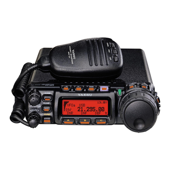
Installation guide for the Yaesu FT857 and FT 857D
Please read through this guide to the end before you begin this installation.
The installation of the BHI module in the 857 is much like the 897. The two radios are virtually the same
design with mechanical packaging the main difference.
The installation of the BHI module in an 857 is very straight forward. However, it is strongly
recommended that you have the proper tools and experience working with tiny Surface Mount
Technology (SMT) components.
There is one part of the installation that needs extreme care. This is the connection to the Main PCB.
Care must be taken to not overheat the board or apply any mechanical force to the pads where C1473 is
mounted. This is especially true on the pad where the blue wire and capacitor are connected. Just like
the 897, this pad is connected to a blind via, meaning the connecting trace is buried inside the layers of
the PCB. If this pad is lifted there is no way to repair that connection. Adding a long jumper wire from
the top of the board to the back side of the PCB is the only functional repair possible. In the installation
steps I will mention some hints I use to have successfully installed many of these modules with no
issues. Keeping in mind that this radio is used for mobile applications, I add a few extra items such as
heat shrink around the BHI module, tie wraps in a couple of locations and 5-minute epoxy to the PCB
leads. This helps prevent any failure due to vibration over time.
steps
Installation
:
Remove the top three screws and 4 side screws. There are two screws for the speaker do not remove
these.
Carefully lift the top cover and disconnect the speaker wire plug.
The BHI switch assembly is best located in the front righthand corner of the
radio. It allows access when the radio is in mobile mounts and go boxes.
Hint (use the top two vent holes as a starting point). I offset drill one hole
and enlarge both holes to match the switch footprint. Other locations can be used, however, I have
found most customers like this location.
Once you have finished modifying the top cover set it aside.
Advertisement
Table of Contents

Related Manuals for Yaesu FT857


Summary of Contents for Yaesu FT857
- Page 1 Installation guide for the Yaesu FT857 and FT 857D Please read through this guide to the end before you begin this installation. The installation of the BHI module in the 857 is much like the 897. The two radios are virtually the same design with mechanical packaging the main difference.
- Page 2 Next: Locate the PCB mounting screw located in the front right corner of the radio. It is just below the ribbon cable connection. Install the BHI ground lug under that screw. Hint (I install heat shrink around the module to prevent any possibility of a short circuit with long term vibration on a mobile radio.) Next solder the red power wire to the output lead of the 8-volt...
- Page 3 When removing C1473 use either a dual SMT tip on a temperature-controlled soldering station or two temperature-controlled irons with small (1/16 inch) tips. It is important to melt the solder on both ends of the cap at the same time and gently lifting the cap off the pads.
- Page 4 The next step is to secure the switch to the double-sided tape on the aluminum bracket provided. Route the switch wires along the top frame of the fan. Use a cut piece of the supplied double-sided tape to hold the switch-bracket in place. This tape is only used to place the switch in position. The compression of the lid to the frame holds the switch in place during operation.
Need help?
Do you have a question about the FT857 and is the answer not in the manual?
Questions and answers