Table of Contents
Advertisement
Quick Links
Advertisement
Table of Contents

Subscribe to Our Youtube Channel
Related Manuals for Vents A21


Summary of Contents for Vents A21
- Page 1 USER’S MANUAL Wireless control system...
- Page 2 www.ventilation-system.com...
-
Page 3: Table Of Contents
Alarm/warning codes ................................. 26 This user’s manual is a main operating document intended for technical, maintenance, and operating staff. The manual contains information about purpose, technical details, operating principle, design, and installation of the A21 unit and all its modifications. -
Page 4: Controller Wiring Diagram
CONTROLLER WIRING DIAGRAM NKP TRIAC NKD TRIAC – Electric shock hazard! www.ventilation-system.com... - Page 5 Controller power supply: 100-250 V, 50 (60) Hz, maximum power consumption – 30 W. Controller inputs Signal Operation Input purpose Input type Designation Comments type logic Outdoor air temperature Analogue NTC 10 -40...120 °C Supply air temperature or temperature Analogue NTC 10 -40...120 °C downstream of the main air heater...
- Page 6 Controller outputs Output Output purpose Signal type Designation Note type Supply fan control Analogue 0-10 V M1 (OUT 0-10) You can configure the minimum and the maximum value of the signal sent to an active fan and the delay before switching to automatic control after activating the unit.
-
Page 7: Connecting A Mobile Device To The Unit
The fan is controlled by the application on the mobile device. The application is available for download at App Store, Play Market or via the QR code. Vents AHU - App Store Vents AHU - Play Market Wi-Fi technical data... -
Page 8: Unit Password Change
UNIT PASSWORD CHANGE Menu ( ) - Connection - At Home. Go to 1. Choose the connection and press 2. Enter and confirm the password (valid characters: 0..9, a .. .z, A .. .Z). Change Password. 3. Press WI-FI PARAMETER SETUP Menu ( ) - Connection - Wi-Fi setup. -
Page 9: Special Setup Mode
SPECIAL SETUP MODE In the event of losing the Wi-Fi password or the unit password, connecting external devices or in other cases, use the special Setup mode to restore access to the unit functions. Setup mode, press and hold the Setup mode To enter the special button on the control panel for 5 seconds before the LED on the... -
Page 10: Creating An Account To Control The Unit Through A Cloud Server
CREATING AN ACCOUNT TO CONTROL THE UNIT THROUGH A CLOUD SERVER MENU ( ) -> CONNECTION -> THROUGH CLOUD SERVER: Open the mobile app and go to 1. To add a new account, press the button. 2. Enter a login, a password and an e-mail address for password recovery. Then press 3. -
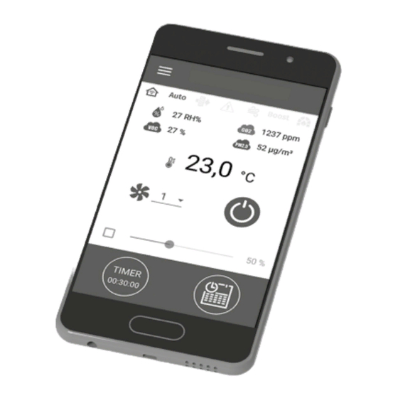
Page 11: Home Page
HOME PAGE Indicators: Current type of unit connection. Home connection or connection via a cloud server through Internet respectively. Current operation mode of the unit. Ventilation only (no temperature control, heat recovery only), ventilation + heating (the unit warms up the outdoor air by means of the ventilation + cooling electric heater or with the outdoor air heat), (the unit... -
Page 12: Basic Settings
BASIC SETTINGS Temperature Menu ( ) - Basic settings - Temperature. Go to Temperature setpoint Select the temperature units for display. Temperature setting for the normal mode (when the timer and weekly schedule mode are disabled). Operating mode: select the operating mode to affect the normal mode, timer and the weekly schedule. Ventilation: •... -
Page 13: Timers
TIMERS Menu ( ) - Basic Settings - Timers. Timer settings are made in the Main timer: Timer mode settings. When the timer is activated in Home page menu, the unit temporarily goes to the following settings: Pre-set speed selection: 1,2,3...,standby. Timer setting. -
Page 14: Date And Time
DATE AND TIME Menu ( ) - Basic settings - Date and time. Go to Current time and date are displayed and adjusted in this menu. hh:mm:ss. Time display format: dd.mm.yyyy. Date display format: FILTER Menu ( ) - Basic settings - Filter. Go to Filter timer setpoint: When the set time (70-365 days) has elapsed, the filter change indicator appears and filter replacement information... -
Page 15: Connection
CONNECTION RS-485 setup Go to Menu ( ) - Connection - RS-485 setup. Default settings: • Controller address: • RS-485 baud rate: 115200 baud. • RS-485 stop bits: • RS-485 parity: none. Note: you can use the RS-485 bus to connect up to 16 units (slave devices) and up to 16 control panels (master devices). The slave and master devices have separate IDs. -
Page 16: Engineering Menu
ENGINEERING MENU Entering engineering menu Menu ( ) - Engineering menu. Go to Enter the engineering password. By default the password is 1111. Menu ( ) - Engineering menu - Engineering password. To change the engineering password, go to Note: the engineering menu requires expert skills. -
Page 17: Air Flow
AIR FLOW Menu ( ) - Engineering menu - Air flow. Go to Standby This menu section enables setting the air flow values for the mode, speed 1,2,3 pre-sets Boost Fireplace as well as the modes. Standby If the air flow value selected for the mode is larger than 0 %, the temperature control function for this mode according to setpoint selected (only +15°С... -
Page 18: Temperature
TEMPERATURE Menu ( ) - Engineering menu - Temperature Go to Current temperature Intake air temperature. Supply air temperature. Extract air temperature upstream of the heat exchanger. Extract air temperature downstream of the heat exchanger. Room temperature (in the controller). Return heat medium temperature. - Page 19 Automatic reduction of the air flow rate. If the main heater cannot heat the temperature in the supply duct to the level of the user-set room temperature, the air flow will be automatically reduced to reach the set temperature. Min. valve position —...
- Page 20 Cooler control mode. manual (on) and auto. If discrete is selected, the cooler can be switched on manually Two options are available: or automatically. If analogue is selected, the 0...100 % cooler control slider appears on selecting the manual mode. Min.
-
Page 21: Sensors
SENSORS Menu ( ) - Engineering menu - Sensors. Go to Main sensor: a wired sensor connected to the control circuit board. External sensor: a remote sensor that may be contained in the control panel or in a special device with a parallel connection to the control panel. -
Page 22: Pid Controller
PID CONTROLLER Menu ( ) - Engineering menu - PID controller. Go to PID controller settings. The Kp, This menu contains factors affect the control signal change rate in response to external factors. Increasing the factor values causes the control signal change faster while decreasing the factor values results in slower control signal changes. -
Page 23: Firmware
FIRMWARE Menu ( ) - Engineering menu - Firmware. Go to This menu displays the current firmware version and date. Check for updates To check for the latest firmware update, connect the unit to a router with Internet access. Then press the button. -
Page 24: Engineering Password
ENGINEERING PASSWORD Go to Menu ( ) - Engineering menu - Engineering password. Use this menu to change the engineering password. ALARMS Menu ( ) - Alarms (Current alarms/Alarm history) Go to The Alarms menu displays a list of alarms and warnings. Alarm records are highlighted in red, warning records are highlighted in black. Alarm A serious operation error has occurred. -
Page 25: Mode Priorities
MODE PRIORITIES Air flow for Fireplace Fireplace ON mode Air flow for Timer ON Timer mode Air flow for Standby ON Standby mode Air flow for Boost ON Boost mode Air flow for Standby Schedule ON Schedule mode mode selected Air flow according 0-10V input to the analogue... -
Page 26: Alarm/Warning Codes
ALARM/WARNING CODES Ordering No. Description Alarm! Supply fan malfunction. • Determined depending on a specific configuration. • By rpm: if the supply fan speed drops below 300 rpm for 30 seconds (configurable within a 5 to 120 second range). • By discrete input: if the discrete input (ТAНО... - Page 27 Warning! Indoor air temperature is not detected! Air management relies on the temperature sensor in the supply air duct. Determined if no sensor data has been communicated from the control panel to the controller for 20 seconds if the sensor is selected as the temperature control master sensor provided that the main heater, the bypass, the rotary heat exchanger or the condensing unit are enabled.
- Page 28 V55-8EN-03...
Need help?
Do you have a question about the A21 and is the answer not in the manual?
Questions and answers