Table of Contents
Advertisement
Quick Links
Advertisement
Table of Contents

Related Manuals for Zubler Z1 - AT


Summary of Contents for Zubler Z1 - AT
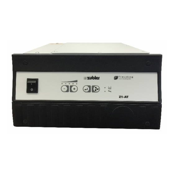
- Page 1 Z1 - AT Single suction system Z1- AT EN 02-2020 www.zubler.de...
-
Page 2: Table Of Contents
Content 0. Intoduction page 0.1 Declaration of conformity 0.2 Intended purpose of use 0.3 Technical requirements 1. Installation of the appliance page 1.1 Scope of supply and accessories 1.2 Installation of the extraction system 1.3 Connection of working tools 1.3.1 Appliances without interface 1.3.2 Appliances with switching output (Potential free e.g. - Page 3 6. Garantie Seite 24 7. Disposal instructions Seite 25 Advanced settings are provided by the Zubler Suction-Technology APP , which is available for Android tablets or phones. Therefore follow the users manual of the Zubler Suction-Technology APP, which is Suction-Technology...
-
Page 4: Declaration Of Conformity
Introduction Dear customer, we are pleased, that you have decided for a Zubler extraction system and hope it will enhance your work. The continuous development of our tech- nology is based on the co-operation with experienced dental technicians. The focus lies on the aim to optimize the extraction technology in the fields of performance, noise and reliability. -
Page 5: Intended Purpose Of Use
0.2 Intended purpose of use This extraction system is designed exclusively for dry dusts! Its use for the extraction of other types of dust or gases must be clarified with the manufacturer before putting into operation. Work must be stopped immediately and the system switched off in the event of the appearance of visible clouds of dust or noticeably insufficient suction power. -
Page 6: Installation Of The Appliance
Installation of the appliance 1.1 Scope of supply and accessories Z1 extraction system Power cord Power adaptor C14 / CEE Special Accessories Order.-No. External control unit 823-020 2m cord incl. Power adaptor C13/C14 012-00306... -
Page 7: Installation Of The Extraction System
The name plate with the Serial-No. is located on the backside of the motor unit 1 (Fig. 3). ZUBLER Gerätebau GmbH Buchbrunnenweg 26 D-89081 Ulm Tel. +49(0)731 1452-0 / www.zubler.de 1 Z1- AT Absauganlage Z1-AT 2 mains power cord Spannung... - Page 8 Mains connection Plug the enclosed power cord into the IEC C14 connector 14 and the mains plug into a local power socket. (Fig. 3) Fig. 3 1.3 Connecting the working tools 1.3.1 Devices without an interface Use the IEC-Schuko power adapter 9 fuses C14 -CEE included in the accessories to 10 vacuum nozzle...
-
Page 9: Intake System
Basic system requirements include optimal particle flow, minimal noise production and ergonomic posture promotion. The following criteria promote these basic requirements and are specifically adapted to Zubler suction systems. Suction funnel R1200, Rectangular pipe R1000, R1300 Rectangular silencer R1100 R1200 Fig. 4... -
Page 10: Control Unit
Functions 2.1 Control unit Fig. 5 2.2 Commissioning The extraction system must be installed and connected as described in section 1. Switch on the main switch 7. L1 LED Power level display One ore more LEDs of the suction L2 LED Bluetoothanzeige level L1 are flashing. -
Page 11: Automatic Operation
2.3 Setting up automatic operation: If a dust producing appliance is connected to the extraction system, the sensitivity must be adjusted for an automatic start of the extractor. The following steps are necessary in order to teach the appliance: The appliance (max. 6A, 120V:600W, 240V:1300W) must be connected to the socket of the extraction system. -
Page 12: Selecting And Saving Suction Levels
While in “Turbo mode” the LED for suction level 5 is flashing. Once the time is elapsed, the suction will fall back to the saved suction level 1-4. Suction-Technology Further adjustments can be made with the Zubler Suction-Technology APP (Android only). -
Page 13: Current Suction Power
In the advanced settings (see section 3) it is possible to set this so that the filter warning is given as soon as the suction power decreases to the next lower suction level. Further adjustments can be made with the Zubler Suction-Technology APP. Suction-Technology... -
Page 14: Fine Tuning Of The Automatic Operation
The suction overrun time can be prolonged by a further 2 sec by repeating the procedure. Further adjustments can be made with the Zubler Suction-Technology APP (Android only). Suction-Technology 2.7 Fine tuning of the automatic operation If the automatic sensitivity matching of the dust producer to the extraction system has not yet led to an ideal result after section 1, the switch-on threshold of the extraction can still be manually readjusted. -
Page 15: Switching The Extraction System Off
The switch-on sensitivity of the T2 (+) button (extraction starts later / less easily; this is a solution if the extraction system occasionally starts up on its own or already runs in standby). Press the Enter button T3 to save the new value Press the fan button T4 to abort the procedure without saving... -
Page 16: Maintenance
Maintenance 3.1 Filter bag replacement For your own safety, replace the filter bag or finefilter cartridge only with appropriate protective equipment (filter mask, protective gloves and suit, safety glasses etc.) Store and dispose the contaminated filters immediately in a dust tight, lockable container (e.g. -
Page 17: Replacement Of The Main Filter
3.2 Replacement of the main filter If the red LED display L4 „Filter“ lights up despite replacing the filter bag, or if the replacement intervals become noticeably shorter, the reason is usually that the fine filter is clogged with dust. To replace the fine filter cartridge, proceed in the following order: For an exchange of the fine filter cartridge proceed as follows:... -
Page 18: Motor
3.3 Motor Due to our innovative motor control, the 5 motor cover wear of the motor and the carbon brushes 17 motor clamp is reduced significantly. Resulting in a 18 motor connector maintenance-free runtime of 1500h. 19 motor Moreover the carbon brushes can be 21 sealing plate changed more often, enabling a total motor lifetime. -
Page 19: Carbon Brush Replacement
Slide the motor module to the front and remove it to the top. Insert the motor vice versa. Take care, that the motor module is inserted on the very front first and must be slided backwards to the sealing plate 21. Fig. -
Page 20: Replacing The Exhaust Filter
3.3.3 Replacing the exhaust filter The exhaust filter must be replaced with every exchange of carbon brushes, since the filter material can not absorb the the debris of multiple brushes. For a replacement of the exhaust filter 22 proceed as follows: Open the exhaust cover 20 by removing the 4 screws TX20. -
Page 21: Status Messages
4. Status Messages Error indication Cause Remedy LED L4 (Filter condition) - Filterbag filled - Replace filterbag, fine - Fine filter or diffusor clog- filter, diffusor - Check intake system, - Intake system, suction suction hose and exhaust hose or exhaust clogged for obstackles - Resistance of intake sys- - Use intake system with... - Page 22 Error indication Cause Remedy Working tool is not working, - Suction unit is switched - Check if the suction unit has no power OFF or not ready is switched ON with main - Fuse(s) 9 is (are) OFF switch 7 - Check if there is a malfunction e.g.
-
Page 23: Technical Data
Technical Data Dimensions: Width: 328mm 12.9” Height: 165mm 6.5” Depth: 385mm 15.2” Weight: 14kg 30.9lb Voltage: AC ±5%, 50-60Hz 230V 110V Power consumption suction: 700W 700W max. power outlet: 1300W 600W max. total power: 2000W 1300W Main fuse: T10A T15A Fuse outlet.: Filter bag Capacity approx.: 3Liters... -
Page 24: Garantie
6. Garantie In case of an appropriate usage, according to the operating manual, we, Zubler GmbH, are granting a warranty of 12 months upon all parts of the suction unit, except wear parts. Wear parts are carbon brushes and dust filtering elements as filterbags, filter cartridges. -
Page 25: Disposal Instructions
Zubler electrical appliances are appliances for commercial use. These appliances may not be taken to municipal collection points for electrical appliances; instead, they are taken back directly by Zubler. You can find out more about current return options online at: www.zubler.de... - Page 26 Notiz...
- Page 28 Zubler Gerätebau GmbH Buchbrunnenweg 26 89081 Ulm-Jungingen Germany...
Need help?
Do you have a question about the Z1 - AT and is the answer not in the manual?
Questions and answers