Table of Contents
Advertisement
Quick Links
S300 Series Dust Monitors
This manual describes how to install and use SINTROL's digital triboelectric
dust monitor S303.
This manual is intended as a guide to the use and installation of the product.
Sintrol shall not be liable for any loss or damage whatsoever arising from use of
any information or details therein, or omission or error in this manual, or any
misuse of the product.
USER'S MANUAL
For S303 Dust Monitor
SINTROL Oy
Ruosilantie 15
00390 Helsinki
Finland.
Tel
+358 9 5617 360
Fax
+358 9 5617 3680
Advertisement
Table of Contents

Related Manuals for Sintrol S300 Series


Summary of Contents for Sintrol S300 Series
- Page 1 This manual is intended as a guide to the use and installation of the product. Sintrol shall not be liable for any loss or damage whatsoever arising from use of any information or details therein, or omission or error in this manual, or any misuse of the product.
-
Page 2: Table Of Contents
Table of Contents INTRODUCTION .................... 3 Safety ......................3 Product overview ................... 4 How does it work ? ..................4 INSTALLATION ..................... 5 Selecting the installation location ..............5 Installing the sensor ..................7 WIRING OF POWER AND OUTPUT CIRCUITS ........8 AC- power connectors (X3) ................ -
Page 3: Introduction
• The particulate may be inflammable, explosive or toxic • The gas can be hot and pressurised The S300 Series dust monitors do not have an internal circuit breaker. The customer has to install a separate circuit breaker to the power cable to ensure that the power can be isolated. -
Page 4: Product Overview
1.2 Product overview The S303 Trend monitor is a microprocessor-based, self-adjusting device, equipped with two alarm relays and a 4-20 mA signal output is designed for trend or filter bag leak detection. It can also be used to detect blockage or stoppage in pneumatic transport and bulk solids handling. -
Page 5: Installation
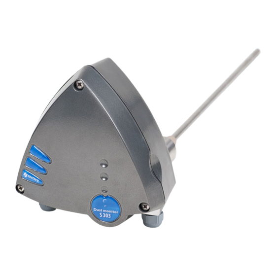
2. INSTALLATION 2.1 Selecting the installation location The best location for installation of the units of the S300 Series is in a section of duct where the particulate has an even distribution and the flow is laminar. This is to ensure that the sensor rod comes into contact with a representative flow of particles. - Page 6 Figure 1. S303 Trend Monitor The unit shall be installed in a position, where the gas flow passes the sensor rod in a 90° angel. In round cross-section ducts, the unit can be installed in any position above the horizontal axis (between 9 o’clock and 3 o’clock). For square cross-section ducts, the unit must be positioned in the middle of the top or in the middle of one of the sides.
-
Page 7: Installing The Sensor
2.2 Installing the sensor Once the location of the unit has been selected, the mounting socket must be welded to the pipe or duct. To do this, first cut a hole in the duct slightly larger than the OD of the mounting socket, 38 mm. The socket must be perpendicular to the flow in the duct. -
Page 8: Wiring Of Power And Output Circuits
3. WIRING OF POWER AND OUTPUT CIRCUITS AC- power connectors (X3) Voltage: 230 VAC +/- 20 V or 115VAC +/- 10V or 24 VDC Frequency: 45 Hz … 65 Hz (AC models) Power cable: 3 x 1,5 mm Connect a 115/230 VAC power supply or a 24 VDC power supply to connector X3 (see Figure 5). -
Page 9: Signal Connector (X5)
Signal connector (X5) One or more of the following functions are available, depending of the product model: Relay output 1: Volt free SPDT contact, max. load 5 A @24 V AC/DC Relay output 2: Volt free SPDT contact, max. load 5 A @24 V AC/DC Analogue output: 4-20 mA, active, isolated. -
Page 10: Technical Specification
4. TECHNICAL SPECIFICATION Measured objects: Solid particles (dust) in a gas stream 0.3 µm or larger Particle size: Measurement range: 0.1 mg/m to 1 kg/m Process Conditions: Temperature: Max. 100°C (standard) / 200-350°C (optional) Pressure: Max. 200 kPa Gas velocity: Min. -
Page 11: Dimensions
5. DIMENSIONS Figure 5. Dimensions and structure of S300 series Dust Monitor enclosure DustMonitor User Manual 21/08/2013 C:\Users\abruniquel\Desktop\S303 User Manual.doc... -
Page 12: Operation
6. OPERATION Operation of the monitor The S300 Series Dust Monitor measures the dust level in a gas stream by monitoring electrostatic discharge when charged dust particles hit or pass by the probe. It may have a 4…20 mA output (S302/S303), and/or two relay contact alarm outputs (S301, S302 and S303). - Page 13 Setup configuration 2: Relay 1 Normally Open (NO), Relay 2 Normally Close (NC), Relay 1 (NO) Relay 2 (NC) Open Close Measuring Relay 2 Dust range High alarm level Close Close concentration Relay 1 Open Low alarm level Close Setup configuration 3: Relay 1 Normally Close (NC), Relay 2 Normally Open (NO), Relay 1 (NC) Relay 2 (NO)
-
Page 14: How To Change Parameter Values
Parameter change buttons A, B and C Figure 8. S300 series Dust Monitor front panel Press the left key (A), below the display, until the left digit indicates the number of the parameter you wish to change, 1 … 8. (see Table 1). -
Page 15: Parameter 1 And 2 - Alarm Relay 1 And Alarm Relay 2 Threshold
PARAMETER CHANGE TABLE DISPLAY KEY EFFECT KEY EFFECT FACTORY PARAMETER RANGE LEFT NUMBER KEY B KEY C DEFAULT Relay 1 trig value 1…99% add 10% add 1% Relay 2 trig value 1…99% add 10% add 1% 4 mA trim increase current decrease current set to 4 mA 20 mA trim increase current decrease current... -
Page 16: Parameter 6 - Analog Output Damping
Parameter 6 - Analog output damping If the dust reading is oscillating , the analog mA output can be averaged by the filter time constant, the filter time can be set between 0 and 60 seconds with 10 seconds increment Parameter 7 - Normal process operation point If the customer wants to change the normal process operation point. - Page 17 Figure 9. Automatic setup button and operation indicator led AUTOMATIC SETUP Ensure that the process is in normal conditions. Make sure that the monitor has been powered for at least 15 minutes in order to warm up and stabilise. Press the AUTOMATIC SETUP BUTTON (the white button on lower printed circuit board) Make sure that green LED indicator turns red Mount the cover of enclosure and tighten it and wait for about 45...
-
Page 18: Maintenance
8. MAINTENANCE S303 Dust Monitor needs very little maintenance. To achieve maximum reliable operation the recommended maintenance interval is 2 months. Maintenance is done by removing the unit from the socket and cleaning the probe to prevent signal leakage to ground. If the particles in the gas are sticky and tend to build up, use air purge adaptor and compressed clean and dry process air to keep the sensor base clean.
Need help?
Do you have a question about the S300 Series and is the answer not in the manual?
Questions and answers