Advertisement
Quick Links
LIQUID INSTALLATION GUIDE
875-0387-100 Rev A1
Overview:
This installation guide lists all the parts in the
IntelliFlow 2 (IF2) liquid kits and provides instructions on how to install
the IF2 components, associated cables, and switches.
Read this manual thoroughly before beginning the installation.
If you have any questions, contact your local dealer or Satloc Customer Service.
IntelliFlow 2 Liquid Installation Guide
1
875-0387-100 Rev A1
Advertisement

Related Manuals for Satloc IntelliFlow 2

Summary of Contents for Satloc IntelliFlow 2
- Page 1 875-0387-100 Rev A1 Overview: This installation guide lists all the parts in the IntelliFlow 2 (IF2) liquid kits and provides instructions on how to install the IF2 components, associated cables, and switches. Read this manual thoroughly before beginning the installation.
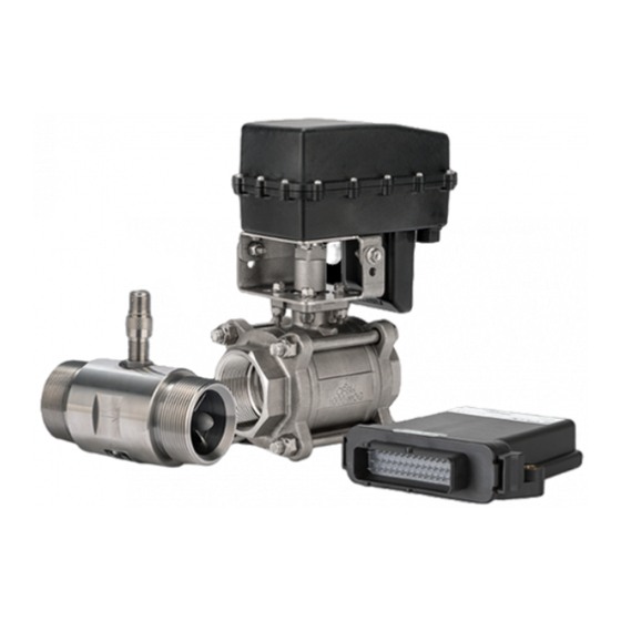
- Page 2 The Satloc G4™ will switch between liquid and dry settings with ease. Control your Transland Hydraulic 5”, 7.5”, or 10” gate system inside the Satloc G4™ and IntelliFlow 2™ connections. The IntelliFlow 2™ control system comes with a controller, associated cabling, and required unlocks. Liquid kits include a valve with a motor and a meter with a magnetic sensor.
-
Page 3: Safety Information
Satloc is dedicated to providing updated versions of installation guidebooks for its customers. Scan the QR code to verify you have the latest version of the IntelliFlow 2 Liquid Installation Guide or click this link to ensure this is the newest version https://satloc.com/products/intelliflow-2/. - Page 4 PARTS COVERED BY THIS INSTALLATION GUIDE This guide is applicable to all IntelliFlow 2 liquid installations for both G4 and Bantam and covers all IntelliFlow 2 kits. Each table describes the parts that may be included in your installation. Table 1: Flow Meters...
- Page 5 Table 3: IntelliFlow 2 Liquid Installation Parts 051-0404-000 051-0403-000 054-0101-000 054-0111-222 Bantam Serial Cable IF2 Power Cable IF2 Motor Cable G4 CAN Cable (1) (red cable) (1) (red cable) (1) (red cable) Connects part I’s TERMINAL cable to (1) (black and white cable) Connects part I’s TERMINAL cable...
- Page 6 (part P) and mount the adapter plate to the aircraft using the existing Legacy IntelliFlow fasteners. Cables and Connections for IF2 Liquid Install Figure 1: Display of How to Connect Cables and Parts for an IntelliFlow 2 Liquid Install Store excess cable lengths with a minimum six-inch bend radius. •...
- Page 7 Install the flow meter and valve/motor assembly in the aircraft’s existing boom supply tube. Figure 2 shows the recommended configuration of IntelliFlow 2’s flow meter and valve/motor assembly. If you cannot install the flow meter and valve/motor vertically (as shown) because of the physical limitations of the aircraft, you may vary the rotational position of either as required.
-
Page 8: Technical Support
2. Secure the hoses using two clamps at each connection. This now constitutes the ‘IntelliFlow2 assembly’ . 3. Attach the IntelliFlow 2 assembly to the boom supply plumbing. 4. Install one or two support fittings from supporting structures of the belly skin of the aircraft close to the valve and flow meter.
Need help?
Do you have a question about the IntelliFlow 2 and is the answer not in the manual?
Questions and answers