
Related Manuals for Microelettrica Scientifica MC20-CEI

Summary of Contents for Microelettrica Scientifica MC20-CEI
- Page 1 MC20-CEI MO-0431-ING Doc. N° OVERCURRENT AND DIRECTIONAL EARTH FAULT PROTECTION ACCORDING TO CEI 0-16 TYPE MC20-CEI OPERATION MANUAL FW 1080.36.03.X 18.11.2011 Microelettrica Scientifica S.p.A. - Copyright 2009 Date Rev.
-
Page 2: Table Of Contents
18. Overall Dimensions (mm) – Protection Degree IP44 (on request IP55) __________________________________________________ 33 19. Direction for PCB's Draw-Out and Plug-In__________________________________________________________________________ 34 19.1 - Draw-Out _________________________________________________________________________________________________ 34 19.2 - Plug-In ___________________________________________________________________________________________________ 34 20. Electrical Characteristics _______________________________________________________________________________________ 35 FW 1080.36.03.X 18.11.2011 Microelettrica Scientifica S.p.A. - Copyright 2009 Date Rev. Pag. -
Page 3: General Utilization And Commissioning Directions
The electronic circuits reduced by M.S. are completely safe from electrostatic discharge (8 KV IEC 255.22.2) when housed in their case; withdrawing the modules without proper cautions expose them to the risk of damage. FW 1080.36.03.X 18.11.2011 Microelettrica Scientifica S.p.A. - Copyright 2009 Date Rev. Pag. -
Page 4: Maintenance
Internal calibrations and components should not be altered or replaced. For repair please ask the Manufacturer or its authorized Dealers. Misapplication of the above warnings and instruction relieves the Manufacturer of any liability. FW 1080.36.03.X 18.11.2011 Microelettrica Scientifica S.p.A. - Copyright 2009 Date Rev. Pag. -
Page 5: General Characteristics
24V(-20%) / 110V(+15%) a.c. 80V(-20%) / 220V(+15%) a.c. 24V(-20%) / 125V(+20%) d.c. 90V(-20%) / 250V(+20%) d.c. Before energizing the unit check that supply voltage is within the allowed limits. FW 1080.36.03.X 18.11.2011 Microelettrica Scientifica S.p.A. - Copyright 2009 Date Rev. Pag. -
Page 6: Operation And Algorithms
Two Phase to Earth Fault Same as A + B Three Phase Fault All the three currents are correctly measured (in any case two directly). FW 1080.36.03.X 18.11.2011 Microelettrica Scientifica S.p.A. - Copyright 2009 Date Rev. Pag. - Page 7 IEEE Very Inverse 3.88 0.0963 IEEE Inverse 5.95 0.18 IEEE Extremely Inverse 5.67 0.0352 The maximum measuring current is “40xIn” for phase elements and “4xOn” for the neutral elements. FW 1080.36.03.X 18.11.2011 Microelettrica Scientifica S.p.A. - Copyright 2009 Date Rev. Pag.
-
Page 8: Time Current Curves Iec (Tu1029 Rev.0)
MC20-CEI MO-0431-ING Doc. N° 2.2.3 – Time Current Curves IEC (TU1029 Rev.0) FW 1080.36.03.X 18.11.2011 Microelettrica Scientifica S.p.A. - Copyright 2009 Date Rev. Pag. -
Page 9: Time Current Curves Ieee (Tu1028 Rev.0)
MC20-CEI MO-0431-ING Doc. N° 2.2.4 - Time Current Curves IEEE (TU1028 Rev.0) FW 1080.36.03.X 18.11.2011 Microelettrica Scientifica S.p.A. - Copyright 2009 Date Rev. Pag. -
Page 10: Funzioni (Functions And Settings)
0.01 (Timer) Stato If disable the function is disactivated (Status) Operation controlled by Blocking Digital Input I>> Trip level (limited to 40 times In) tI>> Trip time delay FW 1080.36.03.X 18.11.2011 Microelettrica Scientifica S.p.A. - Copyright 2009 Date Rev. Pag. - Page 11 (0.05 ÷ 60.00) Tempi tIo>> 0.05 step 0.01 (Timer) Stato If disable the function is disactivated (Status) Operation controlled by Blocking Digital Input Io>> Trip level tIo>> Trip time delay FW 1080.36.03.X 18.11.2011 Microelettrica Scientifica S.p.A. - Copyright 2009 Date Rev. Pag.
- Page 12 If disable the function is disactivated (Status) Operation controlled by Blocking Digital Input Io.2 Trip level Uo.2 Trip level aA.2 First angle trip sector aB.2 Second angle trip sector t67.2 Trip time delay FW 1080.36.03.X 18.11.2011 Microelettrica Scientifica S.p.A. - Copyright 2009 Date Rev. Pag.
- Page 13 Operation: If after the time “tBF” from pick-up of the programmed relay “TrR” the current measured still exceeds 5%In, the output relay associated to the “AnIn” function is operated (relay another than TrR). FW 1080.36.03.X 18.11.2011 Microelettrica Scientifica S.p.A. - Copyright 2009 Date Rev. Pag.
- Page 14 To have Supervision also with the C/B open one N/C contact (52b) from the C/B and an external resistor “R” are needed. ≤ − where = Trip Coil internal resistance [kΩ] V = Trip Circuit Voltage ≥ ⋅ Designe power of external resistance “R”. FW 1080.36.03.X 18.11.2011 Microelettrica Scientifica S.p.A. - Copyright 2009 Date Rev. Pag.
- Page 15 Remote Baud Rate (Rear panel terminal blocks RS485 communication speed) Communication mode (communication parameters) Note: Any change of this setting becomes valid at the next power on Remote Protocol FW 1080.36.03.X 18.11.2011 Microelettrica Scientifica S.p.A. - Copyright 2009 Date Rev. Pag.
-
Page 16: Data Logger
Open “MSCom2” program and connect to the relay (See MSCom2 operation manual) Select “Change Windows” from “Menu” button Select “Event Recorder” to view stored events: A window will appear with all the events recordings FW 1080.36.03.X 18.11.2011 Microelettrica Scientifica S.p.A. - Copyright 2009 Date Rev. Pag. -
Page 17: Export Data Stored
"Save As", choose the destination folder, enter the file name and press Save. Will appear export mode window confirmation If select export (txt) will appear export window confirmation FW 1080.36.03.X 18.11.2011 Microelettrica Scientifica S.p.A. - Copyright 2009 Date Rev. Pag. -
Page 18: Logic Blocking Of Functions
Moreover, the operation of each of the output relays can be programmed to be either Normally Deenergized (energized on tripping of the controlling Functional Element) or Normally Energized (Deenergized on tripping of the controlling Functional Element) FW 1080.36.03.X 18.11.2011 Microelettrica Scientifica S.p.A. - Copyright 2009 Date Rev. Pag. -
Page 19: Digital Inputs
If “ I.R.F. “ is programmed to “ Trip “, the programmed output relays are operated same as on tripping of any protection function If set “NoScatto” (NoTrip), the trip of “I.R.F.” function is recorded in “UltimiSc” (Last Trip) FW 1080.36.03.X 18.11.2011 Microelettrica Scientifica S.p.A. - Copyright 2009 Date Rev. Pag. -
Page 20: Relay Management
LCD display, or remotely via the communication bus RS485 connected to the rear terminal blocks. The 2 line x 8 characters LCD display shows the available information. Key buttons operate according to the flow-chart here-below. FW 1080.36.03.X 18.11.2011 Microelettrica Scientifica S.p.A. - Copyright 2009 Date Rev. Pag. -
Page 21: Signalizations
Give access to any menu or convalidate any programming changement. Reset Return from the actual selected menu to the former menu. Select + Scrolls variables available in the different menus or increases/decreases setting values. Select - FW 1080.36.03.X 18.11.2011 Microelettrica Scientifica S.p.A. - Copyright 2009 Date Rev. Pag. -
Page 22: Serial Communication
Maximum length of the serial bus can be up to 200m. For longer distance and for connection of up to 250 Relays, optical interconnection is recommend. (please ask Microelettrica for accessories) FW 1080.36.03.X 18.11.2011 Microelettrica Scientifica S.p.A. - Copyright 2009 Date Rev. Pag. -
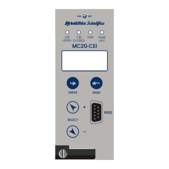
Page 23: Communication Port On Front Face Panel
The physical link is RS232 by the standard female 9-pin D-sub connector available on the Front Face Panel. Via this Port complete Relay management and data acquisition is possible. FW 1080.36.03.X 18.11.2011 Microelettrica Scientifica S.p.A. - Copyright 2009 Date Rev. Pag. -
Page 24: Menu And Variables
Operations counters of Breaker Discrepancy 0 – 65535 Operations counters of Breaker Failure 0 – 65535 Operations counters of trip coil supervision element 0 – 65535 Operations counters of HW recovery operations FW 1080.36.03.X 18.11.2011 Microelettrica Scientifica S.p.A. - Copyright 2009 Date Rev. Pag. -
Page 25: Ultimisc (Event Recording)
Zero sequence voltage ° ° = 0 – 65535 Displacement angle Io-Vo to go back to “ Rec # “, to go back to “ Real Time Meas “. FW 1080.36.03.X 18.11.2011 Microelettrica Scientifica S.p.A. - Copyright 2009 Date Rev. Pag. -
Page 26: Regolazioni (Programming / Reading The Relay Settings)
Rated primary voltage of VT phase to neutral 0.05 - 0.01 Rated secondary voltage of VT phase to neutral 50 - 0.01 Freq System rated frequency 50 - FW 1080.36.03.X 18.11.2011 Microelettrica Scientifica S.p.A. - Copyright 2009 Date Rev. Pag. -
Page 27: Funzioni (Functions)
Operation controlled by Blocking Digital Input Abilit/Disabil. → Livelli Io> 0.50 Trip level 0.01 – 4.00 0.01 → Tempi tIo> 0.50 Trip time delay 0.05 – 60.00 0.01 FW 1080.36.03.X 18.11.2011 Microelettrica Scientifica S.p.A. - Copyright 2009 Date Rev. Pag. - Page 28 Note: any change of this setting became valid 8,o,1 at the next power on 8,e,1 Modbus Remote Protocol Modbus → Livelli Non Disp. → Tempi Non Disp. I Parametri possono essere programmati via porta seriale. FW 1080.36.03.X 18.11.2011 Microelettrica Scientifica S.p.A. - Copyright 2009 Date Rev. Pag.
-
Page 29: Cfg.relè (Relay Configuration)
Digital Input D2 inp3 Digital Input D3 ChInt C/B Close ApInt C/B Open SincDat Date/Hour Synchronization AnIn (BF) Breaker Failure Start Trip Coil Supervision tTCS Trip HwRecov HW recovery operations FW 1080.36.03.X 18.11.2011 Microelettrica Scientifica S.p.A. - Copyright 2009 Date Rev. Pag. -
Page 30: Comandi (Commands)
“ Modello XXXXXX ”, Model Relay “ Ver.Fw. ###.#.#X “, Firmware Version to go back to “ Info&Ver “. to go back to “Misure in tempo reale “ FW 1080.36.03.X 18.11.2011 Microelettrica Scientifica S.p.A. - Copyright 2009 Date Rev. Pag. -
Page 31: Keyboard Operational Diagram
MC20-CEI MO-0431-ING Doc. N° 13. Keyboard Operational Diagram FW 1080.36.03.X 18.11.2011 Microelettrica Scientifica S.p.A. - Copyright 2009 Date Rev. Pag. -
Page 32: Password
OK button when the password is requested. 15. Maintenance No maintenance is required. In case of malfunctioning please contact Microelettrica Scientifica Service or the local Authorised Dealer mentioning the relay's Serial No reported in the label on relays enclosure. -
Page 33: Wiring Diagram
MC20-CEI MO-0431-ING Doc. N° 17. Wiring Diagram 18. Overall Dimensions (mm) – Protection Degree IP44 (on request IP55) FW 1080.36.03.X 18.11.2011 Microelettrica Scientifica S.p.A. - Copyright 2009 Date Rev. Pag. -
Page 34: Direction For Pcb's Draw-Out And Plug-In
Slide-in the card on the rails provided inside the enclosure. Plug-in the card completely and by pressing the handle to the closed position. Rotate anticlockwise the screws with the mark in the vertical position (locked). FW 1080.36.03.X 18.11.2011 Microelettrica Scientifica S.p.A. - Copyright 2009 Date Rev. Pag. -
Page 35: Electrical Characteristics
Tel. (+39) 02 575731 - Fax (+39) 02 57510940 http://www.microelettrica.com e-mail : sales.relays@microelettrica.com The performances and the characteristics reported in this manual are not binding and can modified at any moment without notice FW 1080.36.03.X 18.11.2011 Microelettrica Scientifica S.p.A. - Copyright 2009 Date Rev. Pag.
Need help?
Do you have a question about the MC20-CEI and is the answer not in the manual?
Questions and answers