Table of Contents
Advertisement
Quick Links
Advertisement
Table of Contents

Related Manuals for Metrodata FM4900

Summary of Contents for Metrodata FM4900
- Page 1 FM4900 www.metrodata.co.uk Metrodata FM4900 User Manual Metrodata Ltd Fortune House Crabtree Office Village Eversley Way Egham Surrey TW20 8RY United Kingdom tel: +44 (0) 1784 744700 fax:+44 (0) 1784 744730 email: support@metrodata.co.uk Part No: 76-02-011F website: www.metrodata.co.uk...
- Page 3 Further, Metrodata Ltd reserves the right to revise this publication and to make changes from time to time in the content hereof without obligation of Metrodata Ltd to notify any person of such revision or changes.
-
Page 5: Table Of Contents
CONTENTS INTRODUCTION 1. 1 About The FM4900 1. 2 Typical FM4900 Installation 1. 3 About This Manual 1. 4 Conventions STATUTORY INFORMATION 2. 1 Performance 2. 2 Safety 2. 3 Electromagnetic Compatibility 2. 4 EN55022 Declaration 2. 5 FCC Declaration 2. - Page 6 6. 4 WAN (Line) Port Set-up Menu 6 . 4. 1 Framing 6 . 4. 2 Line coding 6 . 4. 3 Timing 6 . 4. 4 Datalink 6 . 4. 5 AIS Detection 6. 5 DTE Set-up Menu 6 . 5. 1 Interface type 6 .
- Page 7 9. 3 Network Interface (NI) 9 . 3. 1 NI Remote Loop 9 . 3. 2 NI Local Loop 9 . 3. 3 Remote management during testing 9. 4 Troubleshooting FM4900 SPECIFICATIONS 10. 1 FM4900 Default Settings 10. 2 Glossary...
-
Page 9: Introduction
The FM4900 interfaces an E3 service (34⋅368 Mbps) and Data Terminal Equipment (DTE) presenting a High Speed Serial Interface (HSSI) port. FM4900 DSU’s are used in pairs, one at either end of a Wide Area Network (WAN) link. One end is called the LOCAL node, and the other the REMOTE node. -
Page 10: Typical Fm4900 Installation
INTRODUCTION 1. 2 Typical FM4900 Installation ROUTER HSSI FM4900 E3 LINK E3 LINK FM4900 HSSI ROUTER Figure 1. 1 FM4900 typical deployment 76-02-011F... -
Page 11: About This Manual
This user manual describes the installation, commissioning and operation of the Metrodata FM4900 Data Service Unit. It describes the operational functions of the unit, as well as the extensive performance monitoring facilities. A glossary is provided at the rear which explains the abbreviations introduced by this manual. -
Page 12: Conventions
Where menu items are referred to in the text, these are shown in italics to help the reader to cross relate to menu information. Screen examples: the FM4900 allows you to use one of three options for displaying the menus on a terminal - ANSI, VT100/VT220 or TTY. -
Page 13: Statutory Information
34⋅368 Mbps network. The FM4900 maintains bit integrity between the network port and the DTE port. The FM4900 should not be connected to cabling which would be required by BS6701 to be equipped with over-voltage protection. -
Page 14: Power Supply
STATUTORY INFORMATION 2. 6 Power Supply The FM4900 is powered by a mains power supply with an input voltage range 100-250 VAC / 50-400 Hz. The maximum input current is approximately 0.2A rms. at 240V. An alternative -48V DC power supply unit is available, the supply definition being minus 36 to minus 72VDC. -
Page 15: Technical Overview
TECHNICAL OVERVIEW 3 TECHNICAL OVERVIEW The FM4900 is used on unframed G.703 digital services, and can be used in either unframed G.703 or framed E3 G.751 modes. Technical overviews of G.703 and G.751 are provided. 3. 1 G.703 Signal Transmission The signal is transmitted on 75 Ohm RG59 unbalanced coax. - Page 16 TECHNICAL OVERVIEW 76-02-011F...
-
Page 17: Introducing The Fm4900
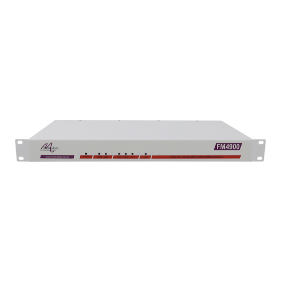
INTRODUCING THE FM4900 4 INTRODUCING THE FM4900 The FM4900 is supplied in a metal enclosure for tabletop or 19” rack mounting using the optional rack mounting ears that bolt onto the side of the module. 4. 1 Front panel Figure 4. 1 FM4900 front panel The FM4900 provides you with essential information through a series of LED’s on the front... -
Page 18: Rear Panel
Figure 4. 3 FM4900 Rear panel 4. 3 Power Supply The FM4900 is powered by a mains power supply with an input voltage range 100-250 VAC / 50-400 Hz. The maximum input current is 0⋅2A rms. at 240V. An alternative -48VDC powered unit is available. The input voltage and current ranges are - minus 36 to minus 72 volts DC. -
Page 19: Remote Management Port
This port contains either a 6-pin mini-DIN connector or a 9-pin D-type connector, allowing you to connect the major and minor alarm relay contacts within the FM4900 to a remote indicator, such as a bell or a lamp. The two types of connectors are described below. The Major alarm contacts are normally open, so that major alarm indication is given if the mains power supply to the DSU should fail. -
Page 20: Terminal Port
INTRODUCING THE FM4900 Function Shield Major common Minor N/O Minor N/C Not connected Major N/C Major N/O Minor common Not connected Figure 4. 6 9-pin D-type connector layout 4. 6 Terminal Port The terminal port is provided for local management of the FM4000. It is a female 25-pin D- type connector with a full RS232 layout which is shown below. -
Page 21: Minimum Rs232 Connection
INTRODUCING THE FM4900 4 . 6. 1 V.24 Terminal Cable 25 Way to 25 Way A full RS232 connection via a 25-way cable is shown below: 25 Way D Male Function 25 Way D (DSU) Female Transmit Receive 4 loop to 6... -
Page 22: Connecting To A Pc Com Port
INTRODUCING THE FM4900 The default settings for the terminal connected to the management port are given in the table below: Item Default Terminal type Baud rate 9600 Parity None Data bits Stop bits Modem support Figure 4.10 Terminal port default settings 4 . -
Page 23: Hssi Port
INTRODUCING THE FM4900 4. 7 HSSI Port The HSSI EIA613 DTE port is used to connect to the router. It consists of a female miniature 50-pin AMP connector, whose pins are described below. AMP connector, part number 749111-4 or should be used for connections to this port. -
Page 24: Network Connection
The port type is classified as 5C (unstructured port) within the scope of OTR.001. The FM4900 provides bit integrity between the E3 port and the DTE port with a worst case round trip delay of 2.4 microseconds. -
Page 25: Installing & Setting-Up
INSTALLING & SETTING-UP 5 INSTALLING & SETTING-UP This chapter describes how to set up the FM4900 ready for use. It covers the initial connections, powering on the unit, and how to access the software that controls the operating parameters. Setting and changing these parameters is covered in Section 6, Configuring FM4900. -
Page 26: Power-Up Sequence
Figure 5. 1 Start-up screens In order to check or change any of the operating parameters, you will first need to gain access to the FM4900's software by logging in. Press any key, and a logon message will be displayed: Metrodata FM4900: Local connection to "[nodename] "... -
Page 27: User Interface
The display of the menu, and the way you select menu options, will depend on which type of terminal you have connected to the unit, and which version of FM4900 firmware you have. This section describes the differences between the three main types of display - how to change the display set-up is described at the end of this section. -
Page 28: Vt100/Vt220 And Ansi Terminals
Framed mode is selected and DATALINK is enabled. The item MANAGEMENT only appears if the LM1100 SNMP Enabler has been fitted to the FM4900. If you press a letter corresponding to a menu option, the value opposite that option will be highlighted. -
Page 29: Default Settings
The default settings for the terminal connected to the management port are given in the table below. The terminal must be set to the FM4900’s default values after performing a cold start. Once this is done, the FM4900’s V.24 settings can be changed using the V.24 SET-UP menu, which is accessed from the MAIN SET-UP menu described in the next section. - Page 30 INSTALLING & SETTING-UP 76-02-011F...
-
Page 31: Configuring The Fm4900
Physical layer stats, Error type, Clear all data Figure 6. 1 FM4900 Menu structure When the FM4900 powers up it automatically seeks to logon to the local node, as described in section 5.2. Pressing the <escape> key on any screen will return you to the previous screen in the structure. -
Page 32: Main Set-Up Menu
Figure 6. 2 Main set-up menu The menu item MANAGEMENT only appears if the LM1100 SNMP Enabler has been fitted. The item REMOTE LOGON only appears if the FM4900 is in G.751 framed mode and DATALINK is enabled. 6 . 2. 1 Alarm extension Selecting the menu item ALARM EXTENSION on the MAIN SET-UP menu leads to a further menu. -
Page 33: Clear Alarm Outputs
The NI PORT option shown below provides a display of all the alarms which are valid for the FM4900. in each operating mode. The alarms are labelled from 0 to 9 and A to Z in the firmware, and can be selected by their label. -
Page 34: General Set-Up Menu
CONFIGURING THE FM4900 6. 3 General Set-Up Menu GENERAL SET-UP Time 16:24:32 Date Mon 2/4/01 Node name “[nodename]” Password tElnet timeout HIGHLIGHTED letter - select item <escape> - exit menu Figure 6.7 General set-up menu Note: the TELNET TIMEOUT option appears only if you are using SNMP or DATALINK facilities. -
Page 35: Node Name
This option is used to change the current password. The supervisory password, which allows you to change settings, is initially set to the model number, i.e. FM4900. If you wish to change the password, select this item and then enter the new password. - Page 36 Binary 3). 6 . 4. 3 Timing This details the clocking employed in the FM4900, and the values are INTERNAL and LOOP. The E3 Line TX clock is derived from the DTE using CCT 113 (TT: terminal timing). The HSSI specification requires this signal to be a non-gated version of CCT 114 (ST: send timing).
- Page 37 The DATALINK facility is only available in G.751 Framed mode. It enables you to control and monitor statistics from the remote FM4900. The options are ON or OFF. When DATALINK is set to ON, The National bit (Bit 12 of the framing overhead described in Section 3) is used to provide 22.375 Kbit/sec of datalink bandwidth.
- Page 38 When FRAMED mode has been selected and DATALINK has been set to ON, a REMOTE LOGON option appears on the MAIN SET-UP menu. When you select REMOTE LOGON, the local FM4900 Telnets across the datalink to the far end unit and allows you to logon to the remote unit directly.
- Page 39 Figure 6. 14 DTE setup menu 6 . 5. 1 Interface type This shows the type of DTE port fitted to the FM4900 - HSSI - and is for information only. 6 . 5. 2 CA This controls the CA (Control Available) signal. It can be set to ON, OFF, or THROUGH.
- Page 40 CONFIGURING THE FM4900 6. 6 V.24 Set-up Menu This screen allows you to set up the communications parameters for the terminal anagement port. V.24 SET-UP Terminal type Vt100/VT220 Baud rate 9600bps Parity None Data bits Stop bits Modem support Load new config HIGHLIGHTED letter - select item <escape>...
- Page 41 Except for the TERMINAL TYPE, the changes you make on the V.24 Set-up screen do not take effect until you register the changes in the FM4900. This is done by selecting LOAD NEW CONFIG after you have made the necessary changes to the other values on this screen.
- Page 42 They can be the first port of call for a network manager when investigating a problem, and serve to confirm the status of the FM4900 at any point in time from the last cold start. If a cold start is performed, this log will be cleared and the first entry in the log will be the date and time of that cold start.
- Page 43 14/5/2001 11:32:38 Config updated Press any key to continue Figure 6. 19 Config event log 6. 9 Performance Data This option gives you access to the FM4900's performance monitoring functions. These are described in detail in Section 7, Analysing Performance. 76-02-011F...
- Page 44 CONFIGURING THE FM4900 6. 10 Unit Set-up Checklist FM4900 DSU’s are used in pairs, one at each end of a WAN link. This section acts as a checklist for setting up each unit before establishing a valid configuration for a particular application.
- Page 45 The first part of this section describes the Errors and Alarms that are valid for the modes of operation of the FM4900. Performance data is displayed in the form of an on-screen report or summary. Information is grouped into periods of 15 minutes. Examples of the screens are shown in later subsections.
- Page 46 The CLEAR ALL DATA option clears the complete performance statistics database. This may be necessary if the FM4900 contains data that is invalid, perhaps because the data was obtained from a different circuit or the unit has been powered down, or reconfigured. You will be prompted to confirm this option.
- Page 47 G.821, or events if the style is set to counts. Remote Alarm Indication: the Remote FM4900 has detected a problem. The units are seconds if the summary style is G.821, or events if the style is set to counts.
- Page 48 ANALYSING PERFORMANCE 7. 3 Performance menu PERFORMANCE DATA Interface Display mode Static summary Summary style G.821 Phys layer stats <display> Error type Clear all data HIGHLIGHTED letter – select item <escape> - exit menu Figure 7. 6 Performance data menu 7 .
- Page 49 G.751 framed mode. In Unframed mode only LOS and AIS (if it has been ENABLED) will be listed. Note: If the real-time clock is altered then the relative times of this database are also modified. Metrodata FM4900: Local connection to “[nodename]” NI Interface 1 of 6 FAS Errors:...
- Page 50 This option is a more economic version of the 15-minute summaries option where a line printer is used, since only one report line is added to the printout every 15 minutes. Metrodata FM4900: Local connection to “[nodename]” NI Interface 1 of 6...
- Page 51 ANALYSING PERFORMANCE 7. 5 Physical layer stats - Summaries 7 . 5. 1 Screen presentation The summary report screens are designed to give a view of the alarm and error status on a single screen. There is a choice of update frequencies of the data so that the user can choose the optimum presentation at any time.
- Page 52 ANALYSING PERFORMANCE 7 . 5. 3 Summary style This option determines the method of presenting the error information in the summaries. These options are not available for the full or rolling reports, which have a fixed style. The SUMMARY STYLE option only shows on the menu when a SUMMARY has been selected in the DISPLAY MODE.
- Page 53 ANALYSING PERFORMANCE 7 . 5. 4 Summary display - COUNTS style Metrodata FM4900: Local connection to "[nodename]" 13:32:54 Tue3/4/2001 PERFORMANCE SUMMARY Current Alarms: None ------------------------------------------------ Diag: None Temporary Current Previous Last Counts 15 mins 15 mins 24 hours Alarm counts...
- Page 54 ANALYSING PERFORMANCE 7 . 5. 5 Summary display - G.821 style Metrodata FM4900: Local connection to "[nodename]" 13:32:54 Tue 3/4/2001 PERFORMANCE SUMMARY Current Alarms: None ------------------------------------------------ Diag: None Temporary Current Previous Last Counts 15 mins 15 mins 24 hours Alarm counts...
- Page 55 ANALYSING PERFORMANCE 7 . 5. 6 Summary display - Percent G.821 style Metrodata FM4900: Local connection to "[nodename]" 13:32:54 Tue 3/4/2001 PERFORMANCE SUMMARY Current Alarms:None ------------------------------------------------ Diag: None Temporary Current Previous Last Counts 15 mins 15 mins 24 hours Alarmed time:...
- Page 56 ANALYSING PERFORMANCE 76-02-011F...
- Page 57 REMOTE MANAGEMENT 8 REMOTE MANAGEMENT In addition to using the terminal port, the FM4900 may be managed remotely by using a LAN-based network management system. In order to do this, the LM1100 SNMP Enabler option must be fitted to the FM4900.
- Page 58 For further information on the management interface and the MIB definition, refer to the LM1100 SNMP Enabler user manual. The MIB definitions supported have been placed in the public domain by Metrodata and can be parsed in to any NMS supporting an ASN.1 MIB parser.
- Page 59 TEST & TROUBLESHOOTING 9 TEST & TROUBLESHOOTING Several diagnostic tests are supported by the FM4900. The fact that the E3 signal is framed is used to identify a faulty or failed connection. In addition loop-backs may be activated to segment the link, and test patterns may be generated or monitored to validate signal flow along the path of the link.
- Page 60 DTE at the DTE interface. The signal from the remote DTE passes through both the FM4900’s and is looped adjacent to the local FM4900’s DTE port. This therefore validates: a) the local DTE cable (without the effect of the FM4900) if the local DTE recognises its own transmissions.
- Page 61 When the EXTERNAL LOOP is ENABLED the FM4900 uses one of the HSSI control lines (LC) to put the local DTE into loop. This validates the E3 link, both FM4900’s and both sets of DTE cables if the remote DTE recognises its own signals.
- Page 62 This therefore validates: a) the remote DTE cable if the remote DTE recognises its own transmissions b) the local DTE cable, the local FM4900 and the E3 link if the local DTE recognises its own transmissions.
- Page 63 9 . 3. 3 Remote management during testing Care must be taken when testing. If the FM4900 is managed with SNMP or Telnet, and if the LAN to which the NMS is connected passes over the wide-area link to which the FM4900 is interfacing.
- Page 64 TEST & TROUBLESHOOTING 9. 4 Troubleshooting Step 1: Establish and verify the E3 Link Check the power LED at both ends. If power is not present, check the mains fuse. Set both units to UNFRAMED mode using the WAN PORT SET-UP menu: If the MAJOR alarm LED is on, try swapping the BNC connections at one end.
- Page 65 FM4900 SPECIFICATIONS 10 FM4900 SPECIFICATIONS Parameter Definition E3 interface G.703 compliant, Sensitivity: -10dB. Line coding: HDB3. Interface type: 75 Ohm unbalanced coax (BNC) Jitter Tolerance: Per G.823. Barrier: EN 41003 compliant barrier provided on both interfaces. Framing: G.751 or G.703 Unframed.
- Page 66 FM4900 SPECIFICATIONS 10. 1 FM4900 Default Settings When a cold start is performed, all values are returned to their default settings. The table below lists the default values. Option Default Node name This field cleared Password FM4900 Telnet Timeout 60 seconds Framing G.751...
- Page 67 FM4900 SPECIFICATIONS 10. 2 Glossary Alarm Indication Signal Alternate Mark Inversion Bursty errored seconds Control Available Degraded minutes Data Service Unit Data Terminal Equipment Error-free seconds Errored seconds FEBE Far End Block Error HDB3 High-Density Binary 3 Local Area Network...
- Page 68 FM4900 SPECIFICATIONS 76-02-011F...
Need help?
Do you have a question about the FM4900 and is the answer not in the manual?
Questions and answers